Use this page to decide whether a hydraulic elevator component can match the existing pump unit, valve block, cylinder, piping, pressure, flow, electrical controls, safety devices, and building interfaces without turning a part replacement into a hydraulic-system redesign.
A hydraulic elevator is a system of mechanical, hydraulic, electrical, and safety interfaces.
The pump unit creates flow. The valve block controls movement. The cylinder converts hydraulic pressure into car movement. Pipes and hoses carry the fluid. The controller commands the hydraulic unit and reads safety and position signals. Rupture valves, one-way restrictors, pressure-related devices, and other safety elements operate within a defined hydraulic circuit. Oil condition, temperature, tank capacity, motor duty, pipe geometry, and the installed load can all change how the system behaves.
That is why a hydraulic replacement should not begin with a question such as “What pressure is this valve?”
Pressure is important, but it is only one field.
Two valves can have similar pressure ratings while using different flow ranges, port sizes, operating logic, coil voltages, adjustment functions, emergency lowering arrangements, or safety-device interfaces. Two pumps can fit the same motor power but produce different flow and noise characteristics. Two cylinders can share the same outside diameter while differing in bore, rod or plunger dimensions, stroke, mounting, sealing, load path, or allowable pressure.
The second failure is replacing a visible component without reconstructing the circuit.
A slow elevator may be blamed on the pump even when the real cause is oil temperature, valve adjustment, internal leakage, motor supply, filter restriction, cylinder leakage, incorrect load, or another part of the hydraulic system.
The third failure is safety substitution. A rupture valve or one-way restrictor is not an ordinary flow-control part when it performs a defined elevator safety function.
ISO 8100-2:2026 explicitly includes verification of rupture valves and one-way restrictors and also covers calculations for rams, cylinders, rigid pipes, and fittings. A visually similar hydraulic component is therefore not automatically an approved replacement.
JAFITA’s current component framework provides the correct starting fields for this category: hydraulic lift architecture, valve or pump data, cylinder and piping interfaces, and pressure-related design information.
The current supplier materials do not establish a standalone JAFITA hydraulic-elevator product line or a published hydraulic-component model catalogue. This page therefore focuses on the engineering information a buyer needs to identify and source components correctly without converting industry hydraulic technology into unsupported JAFITA product claims.
Hydraulic-component specifications should be divided into five groups:
First identify what type of hydraulic elevator is being serviced.
Pressure determines force, flow determines movement rate.
Identify the physical interfaces for the actual part:
Identify components performing safety functions:
For replacement and repeat orders, retain:
The hydraulic circuit cannot be evaluated independently from the complete elevator. Do not compare pressure values without knowing where and under which operating condition they were measured.
Compare hydraulic parts in this order: elevator architecture first, pressure/flow and safety function second, mechanical/electrical interfaces third, model and commercial details last.
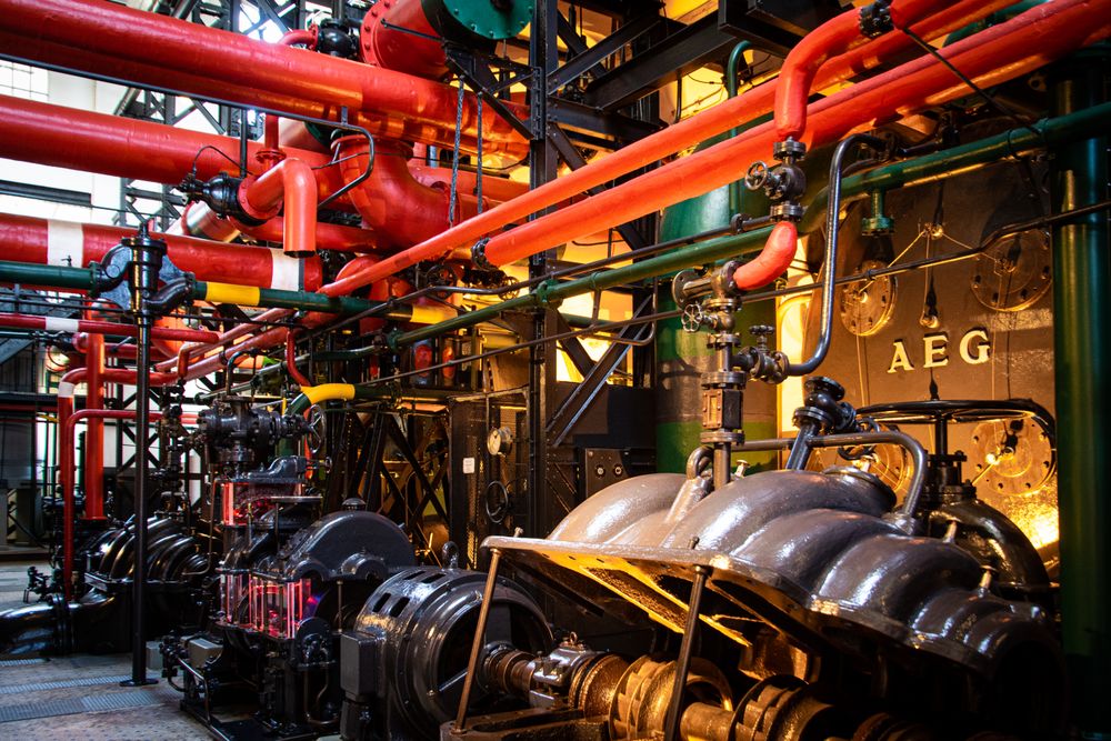
The hydraulic power unit typically combines several functions into one assembly.
Depending on the design, it can include: Electric motor, Pump, Valve block, Oil tank, Filter, Pressure gauge, Relief arrangement, Solenoid valves, Manual lowering device, Temperature-related components, Silencing or vibration-control elements, Electrical terminal or control interfaces.
A complete power-unit replacement should therefore not be selected from motor power or tank size alone. The buyer should identify:
The system has to produce enough flow for the intended movement while generating the required pressure for the actual load and cylinder geometry. A higher-power motor does not automatically improve a hydraulic lift. It can change current draw, electrical supply requirements, heat generation, starting behavior, pump relationship, and cabinet or building services.
Current JAFITA materials do not publish hydraulic power-unit models, motor-power ranges, tank capacities, pump ranges, or noise values.
The pump converts motor input into hydraulic flow.
For replacement, identify:
A pump that fits the mounting and produces similar nominal flow can still behave differently under pressure or temperature. Hydraulic elevator operation can be sensitive to oil viscosity. A system that works acceptably when warm may behave differently after a cold start, while excessive temperature can reduce viscosity and increase leakage or change valve behavior. The pump should therefore be considered together with oil condition, tank, motor, valve unit, and expected operating duty.
For a noise complaint, identify whether the noise comes from the pump itself, motor, coupling, cavitation, aeration, vibration transmission, valve flow, or building structure before replacing the pump.
Current supplier materials do not publish JAFITA pump brands, types, flow ranges, or pressure ranges.
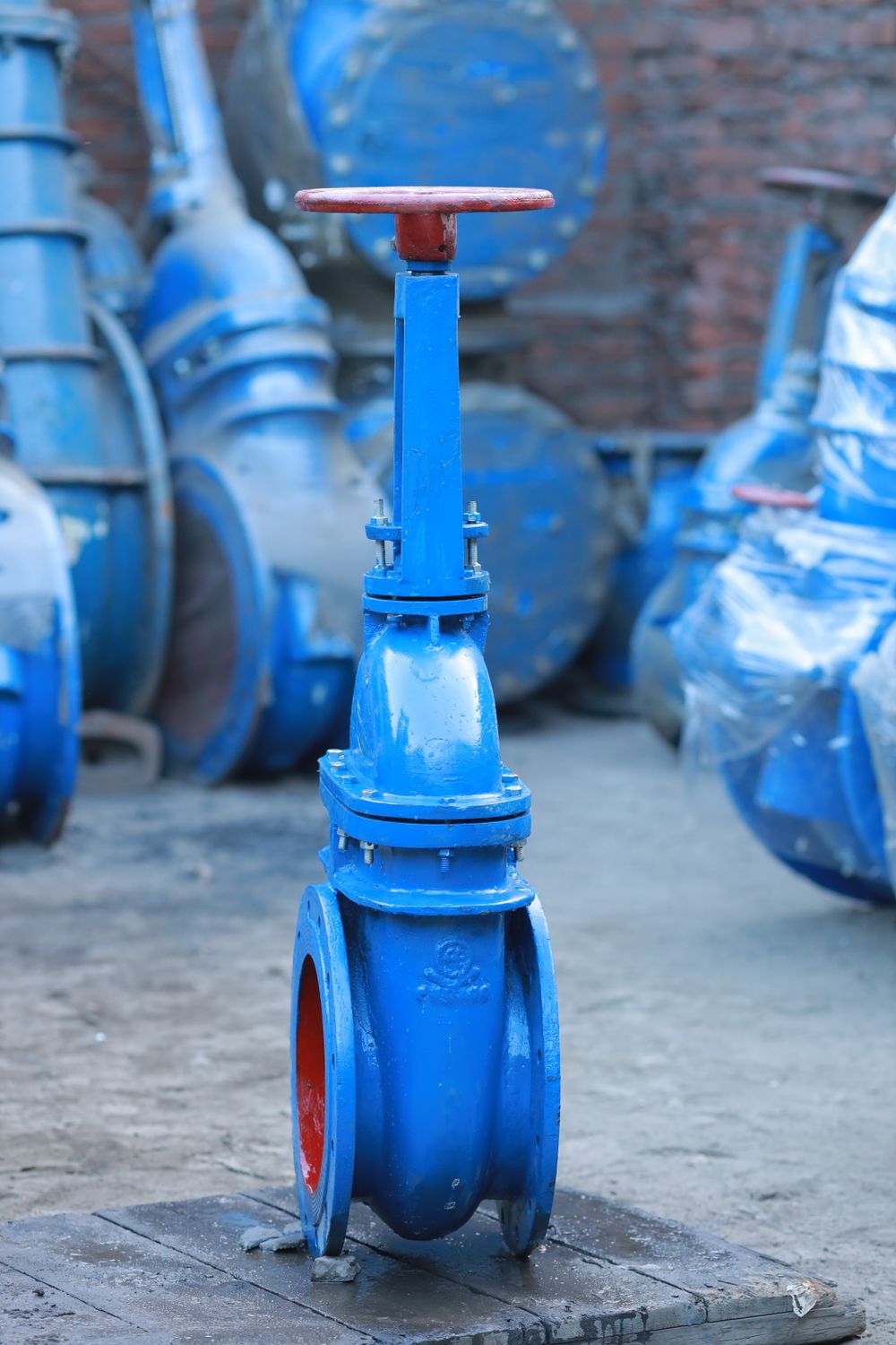
The hydraulic valve block determines how the elevator accelerates, travels, levels, stops, and descends within the selected hydraulic architecture.
A valve replacement should identify:
A mechanically compatible valve can still produce poor ride behavior if its flow-control characteristics or electrical sequence do not match the elevator. Adjustment is also important. Hydraulic valves often contain settings that affect acceleration, deceleration, leveling, or pressure-related behavior. Those settings should not be copied from another elevator with a different load, cylinder, pump, or flow rate.
If a replacement valve also requires different solenoid control, wiring, or controller timing, the job has moved beyond a purely hydraulic substitution.
Current JAFITA materials do not publish hydraulic valve models, flow ranges, pressure settings, coil voltages, or adjustment procedures.
The cylinder is the main force-producing mechanical element of a hydraulic elevator. Its suitability depends on more than bore and stroke.
ISO 8100-2:2026 includes calculations for rams, cylinders, rigid pipes and fittings within its scope for passenger and goods-passenger lifts. This is important because the cylinder must be evaluated structurally, not only hydraulically.
For long slender components, structural stability can become a design issue. A replacement cylinder should therefore be tied to the approved elevator load, stroke, geometry, support arrangement, and applicable calculation. A cylinder with the correct stroke but different mounting or overall length can create pit, shaft, bracket, or piping conflicts.
Current JAFITA materials do not publish cylinder sizes, stroke ranges, pressure limits, seal types, or ram calculations.
Hydraulic elevators can use different mechanical arrangements. In a direct-acting arrangement, the hydraulic ram or plunger acts directly on the car or car frame according to the selected design.
In an indirect arrangement, the cylinder movement can be combined with ropes or chains and sheaves so that car travel differs from ram travel. This distinction changes the component package.
Do not assume that two hydraulic elevators with the same rated load and travel use the same cylinder stroke or hydraulic power-unit requirement.
A rupture valve is a safety-related hydraulic component. Its purpose, within the applicable hydraulic lift architecture, is associated with controlling unsafe downward movement if hydraulic flow changes abnormally because of a failure condition such as a pipe rupture.
The replacement package should identify:
ISO 8100-2:2026 explicitly includes verification of rupture valves and one-way restrictors. That means a generic industrial flow valve should not be substituted merely because the port size and pressure rating appear suitable.
Current JAFITA materials do not publish rupture-valve models, flow ranges, pressure ranges, connection sizes, or certificate numbers.
A one-way restrictor is another component specifically addressed in ISO 8100-2:2026.
The buyer should identify:
A visually similar check valve or flow-control valve is not automatically equivalent. The correct device has to reproduce the approved hydraulic safety function in the exact elevator.
JAFITA’s current supplier documents do not publish a one-way-restrictor product series.
Hydraulic lines connect the power unit, safety devices, and cylinder.
For rigid pipes and fittings, review: Pipe material, Outside diameter, Wall thickness, Pressure rating, Connection type, Fittings, Bends, Supports, Routing, Protection from damage, Corrosion environment, Distance between power unit and cylinder, Existing leakage or vibration issues.
For flexible hoses where used, identify: Hose manufacturer and model, Internal diameter, Pressure rating, Length, End fittings, Bend radius, Movement, Routing, Age or replacement history, External damage, Environmental exposure.
ISO 8100-2:2026 specifically includes calculation of rigid pipes and fittings alongside rams and cylinders. A replacement line should not be selected only by thread size.
Current supplier materials do not publish pipe, hose, or fitting ranges.
Hydraulic fluid affects lubrication, sealing, pump behavior, valve response, heat transfer, and system efficiency. Hydraulic contamination can affect valves, pumps, seals, and small control passages.
Oil Refill/Replacement Fields: Original fluid specification, Viscosity grade, Manufacturer where relevant, Additive requirements, Operating temperature, Ambient temperature, Seal compatibility, Pump and valve requirements, Existing contamination, Water contamination, Previous fluid mixing, Filter condition.
Filter Replacement Fields: Location, Manufacturer, Model, Element model, Micron/filtration data, Flow direction, Flow capacity, Pressure rating, Bypass arrangement, Housing dimensions, Indicator sensor, Fluid type, Service history.
Do not mix fluids solely because both are described as “hydraulic oil.” Changing viscosity can alter leveling, valve timing, leakage, noise, and starting behavior. A filter with finer media is not automatically better if it creates unacceptable pressure drop.
Current JAFITA materials do not publish hydraulic-oil brands, viscosity grades, filter models, or replacement intervals.
A hydraulic modernization should begin with a retained-versus-replaced matrix. Record the status of: Power unit, Motor, Pump, Valve block, Oil tank, Cylinder, Ram/plunger, Rupture valve, One-way restrictor, Relief arrangement, Pipes, Hoses, Fittings, Controller, Position system, COP/LOP, Safety chain, Electrical supply, Emergency lowering, Guide system, Car frame, Car mass, Doors.
Identify why modernization is being performed: Obsolete valve unit, Poor leveling, Excessive noise, Oil leakage, Cylinder leakage, Heat problems, Energy or motor issue, Controller obsolescence, Safety-device replacement, Spare-parts unavailability, Changed car mass, Building renovation.
If a new valve block requires different flow, solenoid control, pump, motor, piping, or controller timing, the work is a system modernization rather than a valve-only replacement. If the cylinder remains, its pressure, stroke, mounting, and condition continue to control the new system. The correct scope is the smallest technically coherent hydraulic system.
These are diagnostic possibilities, not JAFITA-specific failure statistics. The important procurement rule is to isolate the fault before buying the component. A maintenance company should send the fault history, measurements, alarm information, oil condition, photographs, and existing circuit documentation together with the component request.
| Capability | Supplier evidence |
|---|---|
| Component sourcing framework | Hydraulic Components are included in the JAFITA component architecture, with hydraulic lift architecture, valve/pump data, cylinder/piping interfaces, and pressure-related information identified as the required matching fields. |
| Freight manufacturing foundation | JAFITA identifies freight elevator production as a core manufacturing strength. |
| OEM background | Company materials state that JAFITA has provided OEM services for multiple elevator brands. |
| Named OEM history | Uploaded company introduction names KONE and ThyssenKrupp in long-term OEM cooperation. |
| Factory-resource network | Company materials describe direct factory relationships developed through cooperation, including Hitachi and XIO LIFT. |
| International business | JAFITA has been engaged in elevator export business since 2008. |
| Engineering support | Company brochure presents an Engineering Service Team. |
| Lifecycle support | Company brochure presents lifecycle service support. |
| Company qualifications | Company portfolio presents a Special Equipment Production License and ISO 9001, ISO 14001, and ISO 45001 management-system certifications. |
The current supplier evidence does NOT confirm: A JAFITA hydraulic elevator series, Hydraulic power-unit models, Pump models, Valve-block models, Cylinder models, Ram sizes, Pressure ranges, Flow ranges, Hydraulic-oil specifications, Rupture-valve models, One-way restrictor models, Hose or piping products, Hydraulic controller models, or Fixed hydraulic-elevator load or speed ranges.
This page should therefore function as a technically disciplined component enquiry page rather than a claim that JAFITA manufactures or stocks a complete hydraulic range.
For an existing hydraulic elevator, provide:
• For a valve enquiry: Send the hydraulic schematic and photograph every port, coil, label, and adjustment before removal.
• For a cylinder enquiry: Send the complete drawing if available and record bore, ram/plunger dimensions, stroke, retracted and extended lengths, mounting, connection, and shaft geometry.
• For a pump or power-unit enquiry: Include motor information, pressure, flow, oil, tank, installation space, electrical supply, and operating duty.
• For a safety valve: Include the applicable verification or certification documents where available.
Repeat supply should preserve more than the component model. For a hydraulic project, retain:
A valve from the same family can behave differently if settings or coils differ. A pump replacement can affect the valve if flow changes. A new cylinder can change system pressure if its effective area differs. Configuration control therefore has to preserve relationships, not only part numbers.
JAFITA’s OEM history, factory-resource network, Engineering Service Team, lifecycle support, and export activity since 2008 support coordinated project communication and sourcing. Those company-level facts do not establish that JAFITA manufactures hydraulic components in-house or maintains standard hydraulic-component stock.
Can the proposed hydraulic component be traced to the exact circuit, pressure, flow, cylinder, piping, electrical interface, safety function, and approved elevator configuration?
