Use this page to decide whether an elevator suspension system can match the traction machine, car and counterweight masses, reeving, sheaves, terminations, travel, speed, and retained equipment without creating a traction or compatibility problem.
Send Your Suspension Requirements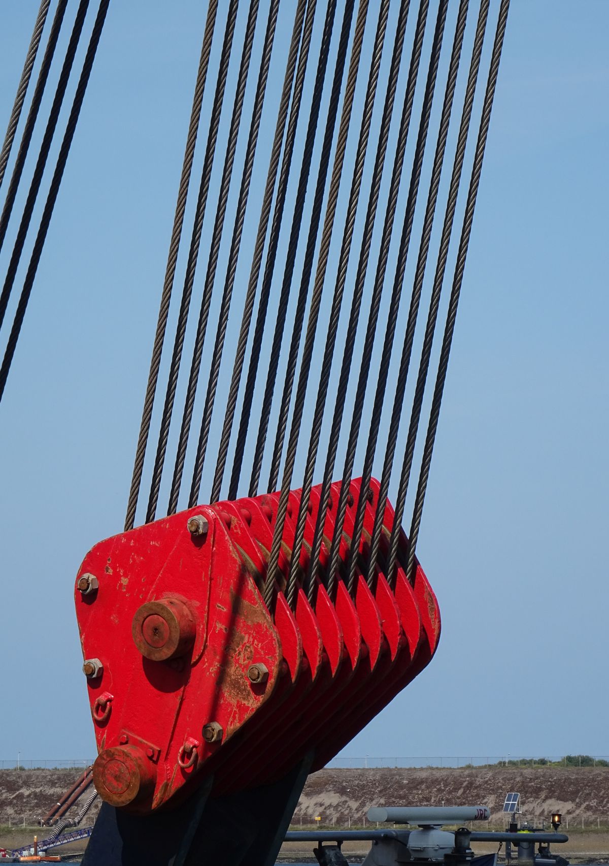
An elevator suspension means is part of the complete mechanical system. It carries and moves the car and counterweight through a defined reeving arrangement, works over traction sheaves and deflection sheaves or pulleys where applicable, terminates at specific hitch points, and must remain compatible with the machine, frame, counterweight, and safety design.
That is why a replacement should not begin with a question such as “What diameter rope do you have?”
Diameter is important, but it is not enough.
Two steel wire ropes with the same nominal diameter can differ in construction, lay, core, tensile characteristics, surface condition, lubrication, elongation behavior, and intended elevator application. A coated suspension medium or flat belt uses a different geometry and different sheave relationship from conventional round wire rope. Terminations, monitoring, inspection methods, and discard criteria can also differ.
A second failure comes from mixing old and new suspension assumptions. Replacing a traction machine while retaining the existing suspension means requires the new sheave and groove geometry to remain compatible with the retained ropes or belts. Replacing ropes while retaining the machine requires the new suspension means to match the sheave, reeving, traction requirement, hitch points, and complete elevator calculation. Changing both can become a system redesign.
A third failure is unequal loading. Suspension means that do not share load correctly can produce uneven wear and affect the traction system. Correct installation, equalization, tension adjustment, terminations, and subsequent inspection therefore matter as much as purchasing the nominally correct rope or belt.
For modernization, the strongest rule is simple: reconstruct the complete suspension architecture before approving any substitute.
Suspension specifications can be divided into selection-driving fields and verification fields.
The selection-driving fields begin with the elevator.
Elevator category, rated load, car mass, and counterweight configuration define the moving system that the suspension means supports. Rated load alone is not sufficient because the ropes or belts interact with the car, counterweight, machine, sheaves, and reeving under different load conditions.
Rated speed and travel affect suspension duty. Longer travel increases the mass of the suspension means themselves and can introduce compensation requirements depending on the elevator design. Higher-speed applications place greater emphasis on the complete dynamic system, including suspension behavior, sheave interaction, car and counterweight guidance, machine control, and installation quality.
Suspension ratio and reeving determine how car movement relates to suspension-medium movement and machine rotation. A 1:1 and 2:1 arrangement do not create the same machine-speed, sheave, hitch, and rope-path relationships. The actual reeving should be shown on the approved elevator drawing rather than inferred from the rope count.
Suspension-medium type comes next. Industry systems can use steel wire ropes, coated suspension media, flat steel-reinforced belts, or other approved suspension means. These are not interchangeable categories. Each requires a compatible sheave or pulley, termination, inspection method, traction design, and applicable verification basis.
Diameter or section is a critical dimensional field, but only inside the selected architecture. For wire rope, nominal diameter does not define construction. For belts or coated media, width, thickness, internal tensile-member arrangement, coating, and manufacturer-specific system design may control compatibility.
Traction-sheave and pulley interface is another selection-driving field. Sheave diameter, groove geometry, groove condition, wrap, material, rope or belt path, and number of suspension means affect the traction and bending environment. ISO 8100-2:2026 explicitly includes verification of suspension and compensation means, discard criteria for suspension means and sheaves, evaluation of traction, and evaluation of the safety factor on suspension means.
Terminations and hitch points must match the suspension medium and car or counterweight structure. Wedge sockets, rope sockets, belt terminations, anchoring devices, equalization arrangements, and other end connections are system-specific. A substitute termination should not be approved because it physically accepts the rope or belt.
Verification fields follow after the architecture is fixed. These include exact rope or belt identification, construction, lay, core, surface treatment, manufacturer markings, batch information where available, termination model, hitch dimensions, sheave data, installation length, quantity, compensation arrangement, drawing revision, and required inspection documentation.
When comparing suppliers, check in this order: first the complete suspension architecture; second the traction, sheave, termination, and frame interfaces; third the exact rope, belt, and accessory identification. A matching diameter alone does not establish equivalence.
Steel wire rope remains a common suspension technology in elevator systems, but “wire rope” is not one specification.
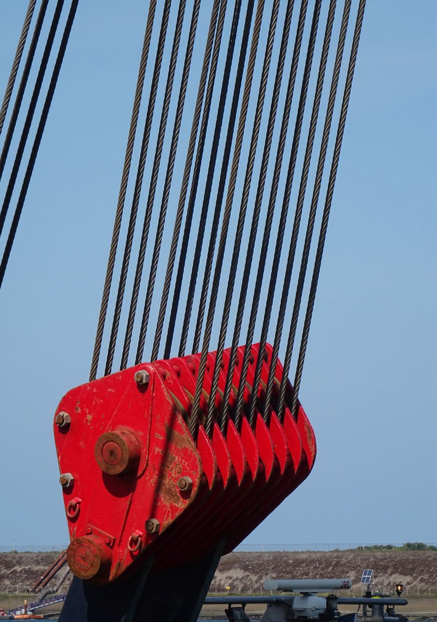
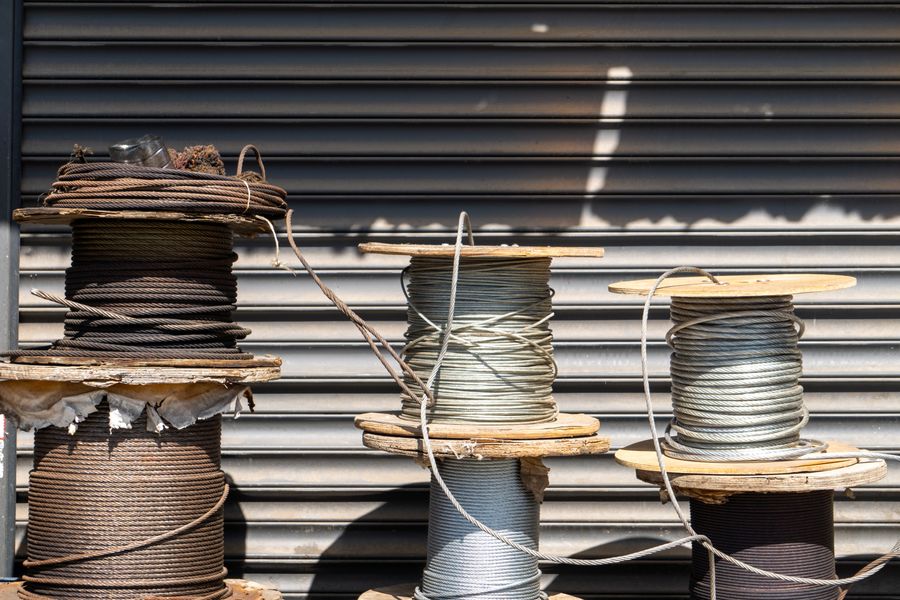
The rope construction defines how wires and strands are arranged and how the rope behaves in bending, traction, wear, and service. Core type, lay, wire arrangement, rope grade or tensile characteristics, lubrication, and surface condition can all matter.
For procurement, the buyer should identify the original rope as completely as possible:
If the original construction is unknown, do not approve a substitute from diameter and visual appearance alone.
The rope also has to match the traction sheave. Groove geometry, groove wear, sheave diameter, wrap, surface condition, and traction calculation affect the relationship. A new rope installed on a worn or incompatible sheave can create a different operating condition from the original system.
Final rope selection and discard criteria should therefore follow the approved elevator design and applicable standard rather than a generic rope table copied from another installation.
Modern elevator systems may use flat steel-reinforced belts or other coated suspension media instead of conventional round steel wire ropes.
The buyer should treat these as complete suspension technologies rather than generic belts.
Belt width and thickness are only the visible geometry. Internal tensile members, coating materials, traction surface, pulley geometry, bending requirements, termination design, monitoring method, and manufacturer-specific compatibility can be equally important. A belt that looks similar cannot be assumed to work with another supplier’s traction sheave, termination, monitoring system, or control strategy.
ASME has developed specific suspension-system standards in addition to its broader elevator safety-code framework. ASME has described A17.6 as the standard addressing elevator suspension, compensation, and governor systems, reflecting the need to treat newer suspension technologies within a defined system rather than as direct wire-rope substitutions.
The current JAFITA supplier materials do not confirm a standalone JAFITA belt range, coated-media range, belt manufacturer, belt dimensions, traction-sheave platform, monitoring system, or termination series. Belts and coated suspension media should therefore be presented only as industry suspension categories that may be encountered in projects, not as documented JAFITA-specific product lines.
For replacement work, provide the original belt or suspension-medium identification, manufacturer, complete markings, elevator model, machine model, sheave or pulley details, terminations, monitoring devices, and photographs before asking for an alternative.
Reeving describes how the suspension means runs between the car, counterweight, machine, sheaves, pulleys, and hitch points.
The suspension ratio changes the relationship between car travel and suspension-medium travel. This affects traction-machine speed and torque requirements, sheave or pulley rotation, hitching, moving suspension mass, and the geometry of the complete shaft arrangement.
That is why a rope or belt order should identify the reeving, not only the elevator speed.
For a replacement project, useful evidence includes the original general arrangement drawing, machine drawing, rope-path drawing, or photographs that show the complete route. Record the number and position of sheaves or pulleys, whether the car or counterweight uses underslung or overhead sheaves where applicable, the hitch locations, and the exact suspension path.
If the replacement changes the suspension ratio or rope path, it is no longer a like-for-like suspension replacement. It can affect the traction machine, support structure, car frame, counterweight frame, clearances, travel, and complete mechanical design.
The suspension means and traction sheave form a matched mechanical interface.
For steel wire ropes, the groove geometry and condition affect how the rope sits in the sheave and how traction is generated. For belts or coated suspension media, the traction surface and pulley geometry belong to the selected system architecture.
The procurement decision should therefore include:
ISO 8100-2:2026 includes both traction evaluation and discard criteria for suspension means and sheaves. This is an important engineering distinction: suspension replacement is not only about whether the rope or belt is new; the condition and compatibility of the sheave system also matter.
If a traction machine is replaced, do not assume the existing ropes can remain until the new sheave geometry, suspension architecture, and traction calculation have been checked. The same rule applies in reverse when the suspension means change but the machine remains.
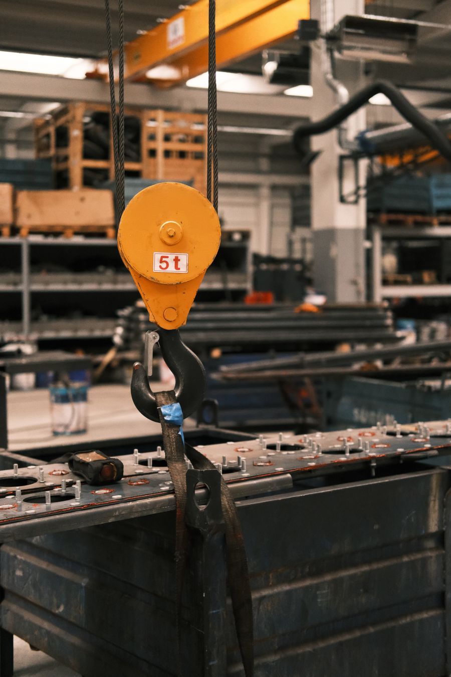
The end connection transfers force from the suspension means into the car, counterweight, support, or other anchoring point.
Different suspension systems use different termination technologies. The correct termination must match the rope or belt type, size, construction, anchoring arrangement, available space, load path, adjustment method, and applicable verification basis.
For wire rope, common industry approaches can include wedge-type sockets and other approved rope terminations. For belts or coated media, the termination is often specific to the suspension system. These industry categories should not be converted into JAFITA model claims without supplier data.
In modernization, record the existing hitch plate, hole pattern, available adjustment, clearances, equalization arrangement, and termination dimensions. If new terminations require a different hitch geometry, the car frame or counterweight frame may also require modification.
A termination that physically holds the rope is not automatically a technically approved elevator termination.
Multiple suspension means are intended to operate as one system.
If load is distributed unevenly between ropes or belts, individual members can experience different tension, wear, stretch, groove interaction, or service conditions. Installation and adjustment must therefore consider the complete set rather than treating each rope independently.
For replacement projects, mixing old and new suspension means within one set should not be assumed acceptable. Differences in construction, elongation history, diameter, wear, or tension behavior can create unequal load sharing. The appropriate replacement practice depends on the actual elevator, suspension system, condition, and applicable rules.
After installation, tension adjustment or equalization should follow the approved product and maintenance instructions. Measurement method, allowable variation, and adjustment procedure should be tied to the suspension system rather than invented as one universal website value.
The current JAFITA materials do not publish a rope-tension tolerance, equalization procedure, measurement method, or maintenance interval. Those values must remain product-specific.
On some elevator systems, compensation means are used to manage changes in suspended mass as the car and counterweight move through the hoistway.
The need, type, and arrangement depend on the elevator design, travel, suspension mass, speed, machine architecture, car and counterweight relationship, and dynamic requirements. Industry solutions can include compensation chains, ropes, or other engineered arrangements, but they should not be treated as universal features.
ISO 8100-2:2026 explicitly includes verification of suspension and compensation means. That makes compensation a defined engineering topic rather than an optional accessory selected from appearance.
For an existing elevator, identify whether compensation equipment is present, its type, routing, attachment, tensioning device where applicable, condition, and relationship with the car and counterweight before any modernization changes the suspension or travel arrangement.
The current JAFITA supplier materials do not publish compensation-chain, compensation-rope, tensioning-device, or long-travel product ranges. These details should be confirmed from project or approved supplier documentation.
JAFITA’s strongest supplier evidence remains in freight elevators. Company materials identify freight elevator production as a core manufacturing strength and describe long-term OEM cooperation in this product area.
That context matters because freight systems can place the suspension and traction system under a different operating pattern from a lightly used passenger elevator.
A distributed pallet load, machinery with concentrated support points, wheeled equipment, forklift entry, or vehicle use changes the car and frame load case. The suspension means still support the complete car system, so the project should be evaluated with the approved car mass, counterweight configuration, traction machine, suspension ratio, and duty.
Operating frequency also matters. A freight elevator used occasionally for deliveries does not necessarily create the same thermal, traction, and wear conditions as one operating repeatedly in a multi-shift industrial process.
JAFITA’s current supplier materials do not publish freight-specific rope diameters, rope constructions, belt types, suspension ratios, rope counts, sheave dimensions, safety factors, termination models, or suspension life. Those values must remain tied to the selected complete elevator.
JAFITA’s brochure presents Passenger Elevator and High-Speed Elevator categories within its broader product scope.
As speed and travel increase, suspension behavior becomes more closely connected with machine dynamics, car and counterweight mass, guide alignment, compensation, vibration, traction, drive control, and the complete building interface.
The buyer should therefore avoid selecting a suspension product because it is described as “high speed” without the associated design information. The correct question is whether the suspension means belongs to the approved machine, sheave, reeving, car, counterweight, guide, and compensation system for the project.
The current JAFITA documents do not publish a high-speed suspension-medium platform or numeric speed, travel, rope, belt, or sheave range. High-speed suspension data should be added only when project-specific technical documentation becomes available.
A modernization project should begin with a retained-equipment matrix.
Identify whether the following will remain or change:
If the traction machine remains, the new suspension means must match its sheave, grooves or traction surface, reeving, and approved traction relationship. If the suspension means remain, a new machine must match them. If both change, review the complete suspension architecture instead of treating the two purchases separately.
Original drawings and component markings are especially valuable. Photographs alone rarely establish rope construction, belt system, termination data, reeving, or traction calculation.
If the original suspension technology is obsolete, the project should decide whether preserving the old architecture still makes technical sense. A change from conventional rope to a different suspension technology is a complete engineering change, not a direct spare-part substitution.
| Capability | Supplier evidence |
|---|---|
| Freight manufacturing foundation | JAFITA identifies freight elevator production as a core manufacturing strength. |
| OEM background | Company materials state that JAFITA has provided freight-elevator OEM services for multiple brands. |
| Named OEM history | Uploaded company introduction names KONE and ThyssenKrupp in JAFITA’s long-term OEM history. |
| Factory-resource network | Company materials describe direct factory relationships developed through long-term cooperation, including Hitachi and XIO LIFT. |
| Passenger project scope | Current brochure presents Passenger Elevator and High-Speed Elevator categories. |
| Freight project scope | Current brochure presents Freight Elevator, Industrial Elevator, and Car Elevator categories. |
| Component coordination | JAFITA’s component architecture identifies Ropes, Belts & Suspension as a technical sourcing category requiring suspension architecture, dimensions, construction, terminations, sheave or pulley interfaces, and equipment identification. |
| International business | JAFITA has been engaged in elevator export business since 2008. |
| Engineering support | Company brochure presents an Engineering Service Team. |
| Lifecycle support | Company brochure presents lifecycle service support. |
| Company qualifications | Company portfolio presents a Special Equipment Production License and ISO 9001, ISO 14001, and ISO 45001 management-system certifications. |
The current supplier materials do not publish a standalone JAFITA suspension catalogue. They do not confirm JAFITA-specific steel-wire-rope constructions, diameters, belt or coated-media products, rope counts, suspension ratios, sheave ranges, terminations, compensation products, safety-factor values, discard limits, service-life values, stock levels, or maintenance intervals.
This page therefore defines the technical information required for sourcing and system matching without converting industry suspension technologies into unsupported JAFITA product claims.
For a new elevator project, provide:
For replacement or modernization, add:
Photographs should show the suspension means, markings, complete machine and traction sheave, rope or belt path, terminations, hitch points, deflection sheaves, car-frame connection, counterweight connection, and compensation equipment where present.
For repeat orders, the suspension record should preserve more than a product name.
Record the approved rope or belt manufacturer and model where applicable, construction, size, quantity, installed length, reeving, suspension ratio, traction sheave, deflection sheaves or pulleys, terminations, hitch points, compensation means, associated machine, drawing revision, and complete elevator identification.
JAFITA’s business model makes this traceability important. The company has a documented freight-elevator manufacturing and OEM foundation, long-term cooperation with multiple brands including KONE and ThyssenKrupp, wider factory relationships including Hitachi and XIO LIFT, export activity since 2008, and an Engineering Service Team with lifecycle support.
Those facts support coordinated sourcing and repeat-project communication. They do not prove that JAFITA manufactures every rope, belt, termination, or compensation component in-house, or that every suspension technology shown in industry standards is part of JAFITA’s current product range.
For professional procurement, the useful question is not “Do you have elevator rope?” It is “Can the proposed suspension means be traced to the exact machine, sheave, reeving, termination, car, counterweight, and approved elevator configuration?” That is the level at which suspension compatibility should be evaluated.
Price can change with suspension-medium type, rope or belt construction, diameter or section, length, quantity, terminations, packaging, manufacturer, certification or documentation requirements, destination, and shipping scope. Compare prices only after the exact suspension system and supply scope are aligned.
The current JAFITA materials do not publish one universal MOQ for ropes, belts, or suspension components. Product source, length, quantity, termination scope, packaging, and shipping arrangement can affect commercial terms.
No fixed suspension-component lead time is published. Exact product identification, length, quantity, terminations, technical confirmation, supply route, destination, and shipping method can all affect schedule.
No. Rope construction, core, lay, tensile characteristics, number of ropes, sheave and groove relationship, reeving, terminations, elevator duty, and original specification also matter.
Do not treat the change as a direct substitution. A belt system can require different traction sheaves or pulleys, terminations, monitoring, machine relationships, suspension calculations, and approved system architecture. A technology change should be engineered as a complete suspension-system modification.
Possibly, but only after the suspension means, traction sheave, grooves or traction surface, reeving, condition, traction requirement, and applicable discard criteria are evaluated. The new machine cannot be approved independently from the retained suspension system.
Do not assume that replacing one member of a multi-rope or multi-belt set is acceptable. Differences in wear, elongation, construction, and tension can affect load sharing. The correct replacement scope should follow the suspension-system design, condition, and applicable maintenance requirements.
The method and allowable variation depend on the selected suspension system and manufacturer or project requirements. The current JAFITA materials do not publish one universal tension tolerance or adjustment procedure.
Provide rope or belt type, size, construction, termination model, hitch geometry, adjustment arrangement, photographs, and the elevator and suspension drawings. A termination should not be selected from rope diameter alone.
In some elevator designs, compensation means manage changes in suspended mass as the car and counterweight travel through the hoistway. The requirement depends on the complete elevator design, travel, speed, suspension mass, and dynamic system.
ISO 8100-2:2026 includes verification of suspension and compensation means, discard criteria for suspension means and sheaves, traction evaluation, and safety-factor evaluation for suspension means within its scope.
ASME A17.1/CSA B44 provides the broader elevator safety-code framework, subject to local adoption. ASME has also developed A17.6 for elevator suspension, compensation, and governor systems. The exact edition and adopted requirements should be confirmed for the jurisdiction and project.
Not in the current supplier materials. Do not convert common industry rope diameters, belt types, or suspension ratios into JAFITA-specific product claims until approved supplier datasheets or project records are available.
JAFITA’s brochure presents an Engineering Service Team and lifecycle support, but it does not establish one universal installation commitment for every rope or belt order. Roping, belt installation, termination, tension adjustment, equalization, traction verification, commissioning, testing, and local inspection responsibilities should be defined for the actual project.
This page supports procurement and project definition for elevator ropes, belts, coated suspension media, terminations, reeving, sheave interfaces, and compensation means. It does not create a universal JAFITA suspension range or approve a product from nominal diameter alone.
Suspension means are connected to the traction machine, traction sheave, deflection sheaves or pulleys, car frame, counterweight frame, hitch points, car and counterweight masses, compensation system, travel, speed, drive behavior, and complete elevator safety design.
ISO 8100-2:2026 specifically covers verification of suspension and compensation means, discard criteria for suspension means and sheaves, traction evaluation, and evaluation of safety factors on suspension means. North American projects commonly use ASME A17.1/CSA B44 together with applicable suspension-system requirements such as ASME A17.6 where adopted.
Special cases including very long travel, high-speed duty, unusual industrial loading, proprietary coated suspension systems, seismic conditions, hazardous environments, severe corrosion, outdoor exposure, or major modernization require project-specific review.
Local installation, suspension adjustment, testing, inspection, maintenance, discard decisions, and regulatory acceptance remain the responsibility of the parties assigned to those functions under the project and jurisdiction.
