Use this page to decide whether an elevator car frame and counterweight arrangement can carry the real load case, fit the hoistway, match the suspension and guide system, and remain compatible with the approved elevator configuration.
The car frame is the structural link between the load inside the elevator and the systems that guide, suspend, stop, and drive the car. That makes it a poor place for assumptions.
A project can stay within the stated rated load and still create a demanding structural condition. A passenger load is normally distributed across the car floor differently from machinery feet, pallet-truck wheels, forklift wheels, vehicle tires, steel skids, or a load with an offset center of gravity. If the frame and platform are selected only from a nominal capacity number, the actual load path can be missed.
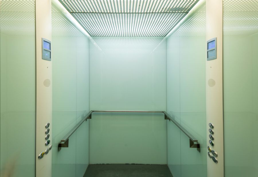
A second failure comes from changing the cabin after the frame has been defined. A wider cabin, deeper cabin, second entrance, heavier decorative package, glass wall, reinforced freight floor, or different door system can change car mass, load distribution, mounting points, and the relationship between the car frame and hoistway. A cabin change is therefore not always a finish change.
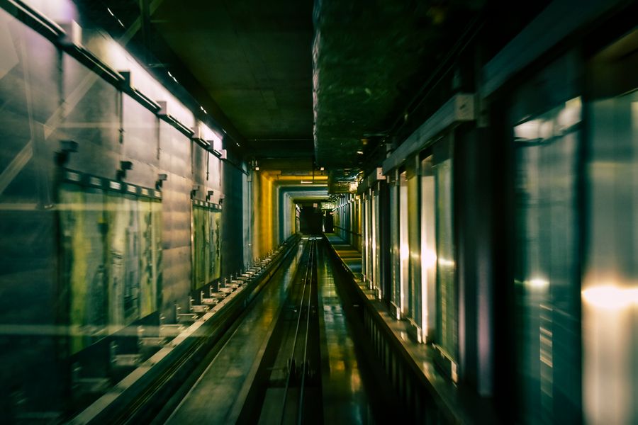
The third failure is a counterweight-space assumption. The counterweight is part of the complete traction and hoistway arrangement. Its location, frame dimensions, guide system, clearances, travel, compensation arrangement where applicable, and relationship with the car affect whether the complete system fits the shaft. A constrained hoistway cannot be evaluated from cabin dimensions alone because the counterweight, guides, doors, suspension, clearances, and other equipment all consume space.
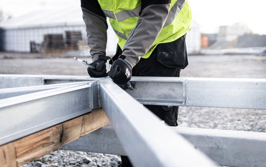
Modernization adds another layer. A new car frame may need to work with retained guide rails, suspension points, traction machine, sheave arrangement, safety gear, buffers, doors, cabin, or counterweight. Replacing one structural assembly without mapping those interfaces can turn a component order into a complete-system redesign.
Car-frame and counterweight specifications should be separated into selection-driving fields and verification fields. The selection-driving fields come first.
Rated load establishes the nominal elevator capacity, but the frame also needs the actual operating load case. For freight work, describe whether the load is uniformly distributed, supported on feet, moved on wheels, carried on a pallet, transported by a pallet truck, entered by a forklift, or represented by a vehicle. The same total mass can create very different reactions at the platform and frame.
Car mass and cabin configuration are part of the structural input. Cabin walls, doors, operators, floors, ceilings, fixtures, glazing, protective panels, and other equipment contribute to the moving mass. A frame should therefore be reviewed against the approved car configuration rather than against an empty cabin shell.
Car dimensions and entrance arrangement affect frame geometry. Front-only, through-car, adjacent, or other entrance arrangements can change the cross-member, upright, platform, and door-support requirements. Large freight doors or unusually proportioned cabins may require a different structural solution from a standard passenger car.
Suspension arrangement connects the car frame to the traction system. The suspension means, hitch points, sheaves or pulleys where applicable, roping or belt arrangement, and load distribution through the frame must be treated as one system. ISO 8100-2:2026 includes verification of suspension and compensation means, evaluation of traction, safety-factor evaluation for suspension means, and guide-rail calculations within its component design and verification scope.
Guide system defines how the car and counterweight are constrained during travel. Guide-rail type and spacing, guide shoes or rollers, frame mounting positions, safety-gear relationships, and hoistway alignment all affect the interface. A replacement frame cannot be approved from width and height alone when the retained guide system is unknown.
Safety-gear interface matters because the car frame is part of the mechanical path through which safety gear acts on the guided car system. Exact mounting, device model, guide-rail relationship, actuation arrangement, and applicable verification basis must match the selected elevator. ISO 8100-2:2026 includes verification of safety gears and guide-rail calculations, but it does not create one universal frame design.
Counterweight arrangement must be defined at system level. The counterweight frame, filler weights or equivalent mass elements, guides, clearances, suspension, and position in the hoistway need to match the traction design and car configuration. Counterweight mass should be established by the elevator design; it should not be estimated independently by a component buyer from a generic percentage rule.
Verification fields come after the main system is defined: Member dimensions, material specifications, weld or bolted-joint details, bracket locations, hitch dimensions, guide-shoe mounting, safety-gear mounting, platform interface, counterweight-frame dimensions, filler-weight identification, drawing revision, coatings, and packing marks.
When comparing suppliers, check in this order: first the real load and car configuration; second the suspension, guide, safety, and hoistway interfaces; third the detailed frame and counterweight drawings. A frame that matches nominal capacity but not the actual interfaces is not an equivalent replacement.
A counterweight reduces the unbalanced load that the traction system must move, but it should not be treated as an isolated block of mass.
The correct arrangement depends on the elevator architecture, car mass, rated load, suspension system, traction design, machine and sheave relationship, travel, guide system, and other project-specific assumptions. The final mass and configuration belong to the approved elevator calculation and drawing package.
The counterweight also occupies physical space throughout the shaft. Its width, depth, frame, guide rails, running clearances, suspension points, buffer relationship, and any compensation equipment have to coexist with the car, doors, brackets, wiring, and other hoistway equipment.
This is particularly important in a modernization or constrained-shaft project. Increasing cabin size or changing the car-frame layout can reduce counterweight space. Moving the counterweight position can affect guide-rail arrangement, machine or sheave geometry, suspension path, structural loads, and building interfaces. A seemingly small space optimization can therefore become a system redesign.
For component procurement, provide the approved counterweight drawing or the complete elevator configuration rather than asking for a counterweight by total mass alone.

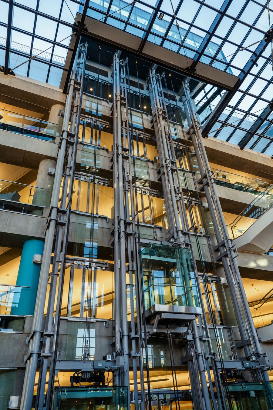
Passenger elevator frames work inside a system where ride behavior, noise, vibration, guide alignment, door operation, and car geometry are interconnected.
As car size, speed, entrance configuration, or finish mass changes, the frame and guide system may also need to change. Observation cabins can add glazing and architectural mass. Medical cabins can have different proportions and door requirements. High-speed projects make system integration increasingly sensitive to guide geometry, dynamic behavior, suspension, and the complete mechanical configuration.
JAFITA’s current brochure presents Passenger Elevator, High-Speed Elevator, Observation Elevator, and Medical Elevator categories. Those product directions support project-level coordination, but the current supplier materials do not publish standalone JAFITA car-frame sizes, section dimensions, permissible car masses, counterweight ratios, guide spacing, or dynamic design ranges for passenger equipment.
The buyer should therefore request a car-frame drawing that is tied to the approved complete elevator rather than selecting a generic frame by passenger capacity.
A front-and-rear entrance can improve material flow by allowing goods, beds, carts, or vehicles to pass through the car without reversing.
Structurally, however, the second entrance changes the enclosure and door-support arrangement. It can reduce available wall structure, change frame and platform interfaces, add door equipment, and shift mass distribution. It also changes the building because two landing openings, two door systems, and additional control logic must be coordinated.
For freight and industrial applications, the project should map the complete route before choosing a through-car configuration. If the load still has to make a tight turn outside one landing, the extra entrance may move the bottleneck rather than eliminate it.
Final frame geometry should be based on the approved entrance and loading arrangement, not added after the frame has been selected.
Forklift and vehicle access changes the structural problem.
The elevator may carry the payload, handling equipment, and operator at the same time. The load reaches the car floor through wheels or tires, creating concentrated contact points. During entry, part of the load can be on the landing and part on the car, while the equipment crosses the sill and aligns with the platform.
Vehicle elevators add axle distribution, wheelbase, track width, overhang, and changing vehicle mix. A gross vehicle mass alone cannot define the frame or platform duty.
JAFITA’s brochure presents Car Elevator as a related freight product direction, but it does not publish vehicle limits or forklift entry limits. These projects must remain project-specific until the actual operating load case and equipment configuration are verified.
Counterweight replacement may appear simpler than car-frame replacement, but the design relationship is still system-level.
A change in cabin mass, rated load, machine, suspension, or traction design can affect the counterweight requirement. A change in counterweight frame size can affect shaft clearances and guides. A change in filler-weight arrangement can affect how the mass is secured and distributed within the frame.
For an existing elevator, do not recreate the counterweight from an assumed percentage of rated load. Use the original design records where available and verify the current car configuration, machine, suspension, guide arrangement, frame, and required clearances.
If original records are incomplete, the project may require a broader engineering review before a new counterweight configuration is approved.
Freight projects are where rated load most often fails to describe the complete structural duty.
A machine on four steel feet, a pallet truck with small wheels, a forklift, or a vehicle can create concentrated forces that differ substantially from a uniformly distributed load. Entry and braking can also introduce local effects at the floor and platform. If the load is offset, the car frame and guide system may see different reactions from a centered load of the same mass.
JAFITA’s supplier evidence is strongest in freight elevators. Company materials identify freight elevator production as a core manufacturing strength. The current freight-elevator brochure also presents a High-strength Structure as a product theme, alongside Industrial Elevator and Car Elevator categories.
That supplier evidence is relevant to a car-frame discussion because it confirms a freight-oriented structural direction. It does not provide a numeric JAFITA frame capacity, floor-loading limit, concentrated-load limit, wheel-load limit, axle-load limit, member size, material grade, weld specification, or allowable deflection.
For a freight enquiry, provide:
The frame, platform, guides, doors, suspension, and building reactions should then be reviewed as one structural system.
A replacement car frame is one of the more consequential modernization components because it connects to several retained systems.
Begin by identifying what will remain. If the guide rails remain, record rail profile, spacing, bracket arrangement, guide-shoe or roller interfaces, and condition. If the safety gear remains, record model, mounting, actuation, rail compatibility, and how it attaches to the frame. If the suspension remains, record hitch points, rope or belt data, sheave arrangement, suspension ratio, and machine relationship. If the cabin and doors remain, record their dimensions, mass, entrances, and mounting points.
Then record the existing platform, frame dimensions, crosshead, uprights, lower frame, counterweight position, buffers, hoistway clearances, and approved drawings.
A replacement frame that requires different guides, safety gear, hitch geometry, cabin supports, or suspension may no longer be a direct component replacement. It may be a broader modernization package.
Photographs help identify the equipment, but dimensional drawings and original records are much more valuable for structural compatibility.
| Capability | Supplier evidence |
|---|---|
| Freight manufacturing foundation | JAFITA identifies freight elevator production as a core manufacturing strength. |
| Freight structural direction | Current freight-elevator materials present a High-strength Structure as a product theme. |
| Industrial project direction | Industrial Elevator is presented in the current freight product range. |
| Vehicle project direction | Car Elevator is presented in the current freight product range. |
| OEM manufacturing background | Company materials state that JAFITA has provided OEM services for multiple elevator brands. |
| Named OEM history | Uploaded company introduction names KONE and ThyssenKrupp in JAFITA’s long-term OEM history. |
| Factory-resource network | Company materials describe direct factory relationships developed through long-term cooperation, including Hitachi and XIO LIFT. |
| Passenger product scope | Current brochure presents Passenger, High-Speed, Observation, and Medical Elevator categories. |
| Home customization context | Home Elevator materials support multiple size customization, which can require project-specific car-system coordination. |
| International business | JAFITA has been engaged in elevator export business since 2008. |
| Engineering support | Company brochure presents an Engineering Service Team. |
| Lifecycle support | Company brochure presents lifecycle service support. |
| Company qualifications | Company portfolio presents a Special Equipment Production License and ISO 9001, ISO 14001, and ISO 45001 management-system certifications. |
The current supplier materials do not publish a standalone JAFITA car-frame or counterweight catalogue. They do not provide frame model codes, member sizes, steel grades, car-mass limits, rated-load ranges, concentrated-load limits, guide spacing, suspension ratios, safety-gear interfaces, counterweight ratios, filler-weight dimensions, counterweight-frame sizes, or structural test data.
JAFITA-specific numeric claims should be added only when actual car-frame, platform, counterweight, and complete-elevator technical documents are available.
For a new elevator, provide the project country, elevator category, rated load, rated speed, travel, stops, car dimensions, entrance arrangement, shaft dimensions, cabin mass or finish information where available, and the intended suspension and guide configuration if already defined.
For freight and industrial projects, the load description is mandatory. Add the support or wheel pattern, handling equipment, center of gravity where relevant, entry direction, operating frequency, and any exceptional loading case such as forklift entry, machinery transport, or vehicle use.
For a replacement or modernization, provide:
The technical team can then determine whether the requirement is a direct replacement, a compatible redesigned assembly, or part of a wider modernization.
For structural elevator components, repeatability means more than reproducing the visible dimensions.
The approved configuration should preserve the load case, rated load, car mass, cabin dimensions, entrance arrangement, suspension, guide rails, safety gear, frame geometry, platform, counterweight arrangement, major component relationships, and drawing revision.
JAFITA’s freight-elevator manufacturing and OEM background is relevant here. The company identifies freight production as a core strength and states that it has provided OEM services to multiple brands, including KONE and ThyssenKrupp. Its freight product presentation also emphasizes a High-strength Structure. These facts support discussion of structural coordination and repeat production to defined project requirements.
The company also works across other elevator categories through established factory relationships and project coordination. That means the supply route and approved technical package should remain identifiable for every order rather than implying that one universal JAFITA frame platform covers passenger, freight, medical, home, and other elevators.
The current supplier documents do not state a universal car-frame inspection procedure, weld standard, material traceability method, dimensional tolerance, counterweight weighing procedure, proof-load test, frame-specific production capacity, fixed warranty, or stock policy. Those points should be confirmed against the actual product, manufacturing route, inspection plan, and contract.
Price can change with rated load, car dimensions, car mass, entrance arrangement, platform structure, suspension architecture, guide interfaces, safety-gear mounting, freight load case, customization, quantity, and shipping scope. Compare quotations only after the structural and interface scope is aligned.
The current JAFITA materials do not publish one universal car-frame MOQ. Quantity, customization, manufacturing route, whether the frame is supplied with the platform or cabin, and packaging can change the commercial structure.
No fixed car-frame lead time is published. A useful schedule should follow load-case confirmation, drawing approval, interface confirmation, material and fabrication planning, inspection requirements, packing, and shipment.
No. Car dimensions, car mass, suspension, entrances, guides, safety gear, platform structure, and the actual load distribution all affect the frame requirement. Freight projects also need wheel, foot, skid, axle, or other concentrated-load information where applicable.
Not automatically. The forklift, payload, operator, wheel loads, axle distribution, entry condition, platform, and approach geometry must be evaluated as one operating case. Rated load alone does not prove suitability.
A mass value is not enough for a complete replacement. The frame, dimensions, filler-weight arrangement, guides, suspension, clearances, buffer relationship, and traction-system design must also match the elevator.
Do not use a generic percentage rule as a procurement specification. The required counterweight configuration belongs to the complete elevator design and depends on the actual car, rated load, traction system, suspension, and other design assumptions.
Possibly, but the change must be reviewed against the complete elevator. Increasing cabin mass can affect balance, traction, machine loading, suspension, energy use, and other system calculations. Treat it as a technical change, not a decorative revision.
It may be possible if the rail profile, spacing, guide arrangement, safety-gear model, mounting, actuation, frame geometry, and applicable verification remain compatible. Verify the retained system before approving the frame.
The final requirement depends on the destination jurisdiction and elevator category. ISO 8100-1:2026 provides safety rules for passenger and goods-passenger lifts within its scope. ISO 8100-2:2026 covers multiple component calculations and verifications, including suspension means, traction evaluation, safety gears, and guide-rail calculation. North American projects commonly use ASME A17.1/CSA B44 and local adoption.
Not in the current supplier materials. Frame models, structural ranges, counterweight design data, and project-specific calculations should be added only from actual JAFITA or approved supplier technical documentation.
JAFITA’s brochure presents an Engineering Service Team and lifecycle service support, but it does not establish one universal overseas installation commitment. Lifting, installation, alignment, roping, counterweight assembly, safety-device work, commissioning, testing, and local inspection responsibilities should be agreed for the project.
This page supports project definition and sourcing of elevator car frames, platforms, and counterweight assemblies. It does not create a universal JAFITA structural range or approve any frame from rated load alone.
The car frame is connected to the cabin, platform, suspension, traction system, guides, safety gear, doors, buffers, counterweight, and hoistway. The counterweight is connected to the same overall mechanical and traction design. Changing either assembly can affect multiple safety- and performance-related interfaces.
ISO 8100-1:2026 applies to passenger and goods-passenger lifts within its stated scope, while ISO 8100-2:2026 addresses design calculations, verifications, and tests for several lift components and mechanical relationships. Special conditions such as seismic design, hazardous environments, severe outdoor exposure, unusual industrial loads, firefighting or evacuation functions, and other project-specific duties require additional review.
Building structure, local installation, alignment, adjustment, inspection, and acceptance remain the responsibility of the parties assigned to those functions under the project and jurisdiction.
