Use this page to determine whether a traction machine matches the elevator’s suspension, speed, load, brake, drive, feedback, mounting, and sheave interfaces before it is approved.
Send Your Traction Machine Requirements
A traction machine is not selected by kilowatts alone.
The most expensive replacement mistakes usually begin when the old machine is identified only by motor power, rated load, or a photograph. Those fields describe part of the duty, but they do not define how the machine interacts with the suspension system, traction sheave, brake, encoder, inverter, controller, counterweight, car mass, and building structure.
The first failure is sheave mismatch. A traction sheave has a defined diameter, groove geometry, rope or suspension interface, and relationship with the elevator’s reeving arrangement. Changing that geometry can change traction conditions, rope bending, rotational speed, torque demand, car speed, and the way the complete suspension system behaves. A machine that physically fits the machine room can still be technically incompatible with the existing ropes or belts.
The second failure is brake and feedback mismatch. The brake is part of the elevator safety architecture, while the encoder or other position-feedback device is part of the drive and control loop. A replacement machine with a different brake voltage, brake arrangement, encoder type, signal format, connector, or resolution can require changes elsewhere in the control system. The machine should therefore be evaluated with the controller and drive, not as an isolated motor assembly.
The third failure is mounting mismatch. Base dimensions, fixing points, traction-sheave position, rope lead, reaction loads, and maintenance space all affect whether the machine can be installed safely.
The buyer’s decision is not “Can this machine deliver enough power?” It is “Can this machine reproduce the required mechanical, electrical, braking, feedback, traction, and structural interfaces of the elevator system?”
The selection-driving fields begin with the elevator rather than the machine.
Rated load and rated speed define the operating requirement, but they must be interpreted with car mass, counterweighting, suspension ratio, travel, acceleration profile, traffic or duty, and the total moving system. A 1:1 suspension arrangement and a 2:1 arrangement do not impose the same machine speed and torque relationship for an otherwise similar car movement.
Suspension data comes next. The buyer needs to identify whether the system uses steel wire ropes, coated suspension media, belts, or another approved suspension means, together with the number, diameter or section, and reeving arrangement. Sheave diameter and groove form must match the selected suspension system. ISO 8100-2:2026 specifically includes verification of suspension means, discard criteria for suspension means and sheaves, traction evaluation, and safety-factor evaluation within its scope.
Motor and drive architecture are another group of selection fields. Industry traction machines may use geared or gearless arrangements and different motor technologies. These categories should not be treated as interchangeable labels. They change rotational speed, torque, machine dimensions, brake arrangement, lubrication requirements where gearing is present, and the drive parameters required by the inverter.
The Brake: The brake is a selection-driving field because its mechanical and electrical characteristics must work with the complete lift safety design. Brake type, coil voltage, release monitoring, control arrangement, and available torque cannot be substituted from appearance alone.
Feedback: Feedback is equally important. Encoder or resolver type, electrical interface, pulse or position information, mounting, connector, and compatibility with the inverter and controller can determine whether the machine can be commissioned without additional system changes.
Verification Fields: Verification fields include base dimensions, shaft centerline, sheave position, machine mass, terminal arrangement, temperature sensors, insulation information, brake wiring, encoder wiring, documentation, and identification labels.
Compare machines in this order: first the elevator duty and suspension architecture, second the sheave, brake, drive, and feedback interfaces, and third the physical mounting and documentation. Motor power should be checked within that system, not used as the first matching criterion.
A useful traction-machine enquiry should reconstruct the mechanical relationship between the elevator and the machine.
Start with rated car speed and the suspension ratio. These determine the required rope or suspension-medium speed and therefore influence traction-sheave rotational speed. The effective sheave diameter then links rotational speed to linear suspension speed.
Next define the load system. Rated load alone does not describe the torque required at every operating condition. Car mass, counterweight mass or balance ratio, suspension masses, travel, acceleration, and the required operating cycle all affect machine and drive duty.
Traction must then be checked. The relationship between the traction sheave, groove geometry, suspension means, wrap, loading condition, and system forces must provide adequate traction without creating unacceptable conditions for the suspension system. ISO 8100-2:2026 includes traction evaluation and suspension safety-factor requirements because these relationships cannot be reduced to one catalogue number.
The structural interface should be reviewed in parallel. Base geometry, machine position, load paths, beam or support arrangement, rope lead, clearances, and access for installation and maintenance all affect the usable machine configuration.
For a replacement project, use the original drawing and nameplate where possible. If those are unavailable, measure the installed machine before removal and document the complete suspension and mounting geometry.
Final machine rating, brake capacity, sheave configuration, motor data, encoder, mounting, and inverter parameters must be confirmed for the actual elevator and applicable code.
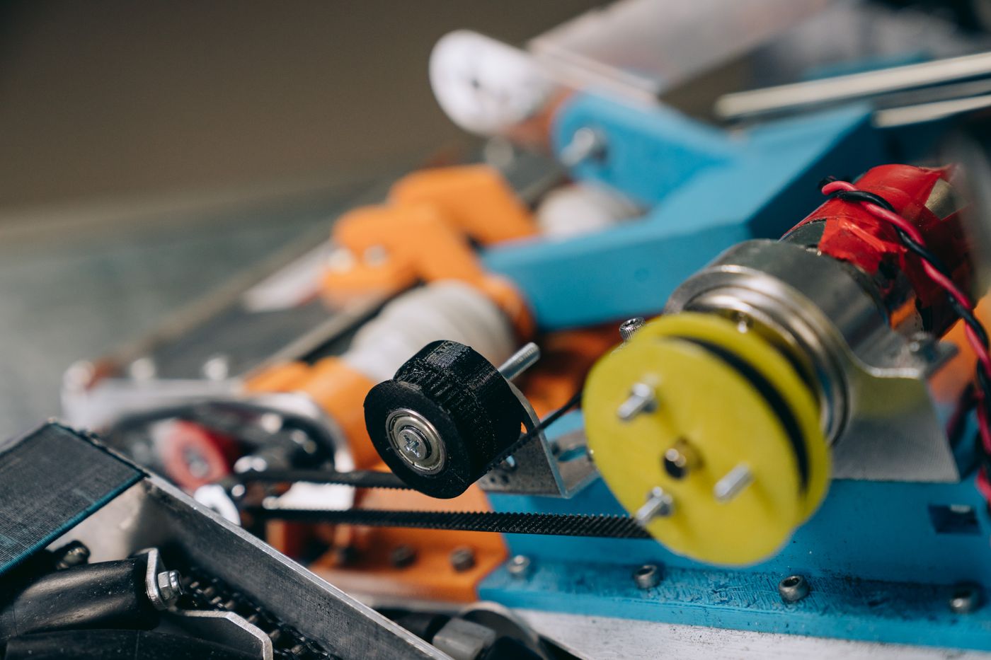
Gearless traction machines couple the motor more directly to the traction sheave because there is no reduction gearbox between them. In modern lift engineering, permanent-magnet synchronous motor architectures are commonly associated with gearless systems, but that industry pattern should not be converted into a claim about JAFITA’s current model range without supplier data.
For the buyer, the decision driver is integration with the inverter and feedback system. Motor voltage, current, torque characteristics, pole arrangement, encoder or resolver, thermal sensors, brake control, and commissioning parameters must match the drive architecture.
A gearless machine can also change the physical arrangement of an existing installation. Sheave position, base dimensions, machine mass, shaft loads, and maintenance access may differ from the machine being replaced. A modernization proposal should therefore show how the new machine aligns with the retained suspension path and support structure.
Do not assume that replacing a geared machine with a gearless machine is a component-for-component exchange. If the change also affects the drive, encoder, controller, brake control, support steel, or suspension path, it is a system modernization.
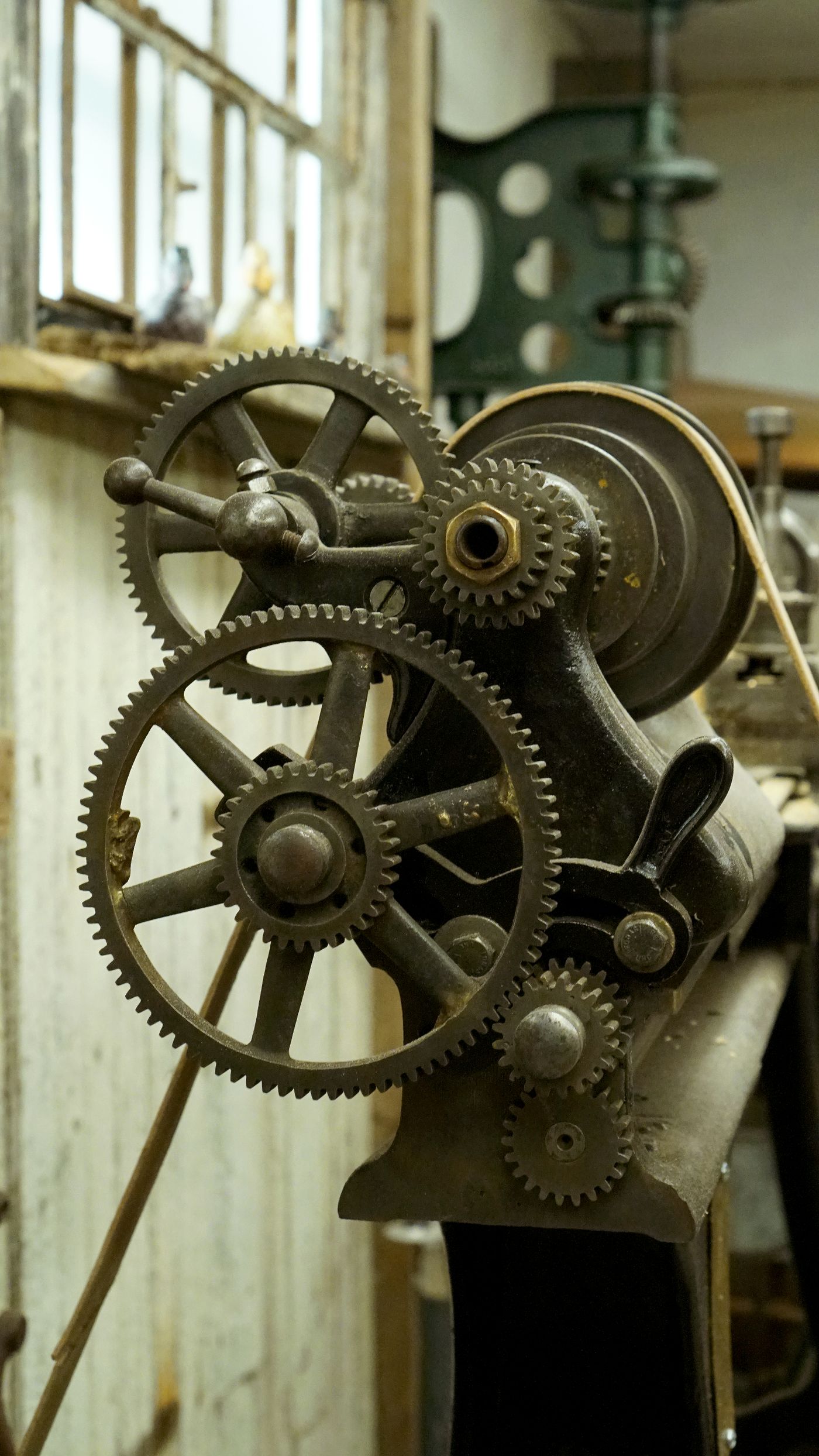
Many existing elevators were designed around geared traction machines. Where the original machine remains serviceable in concept but requires replacement, the strongest constraint is often the equipment that will remain.
The replacement must be evaluated against the existing suspension arrangement, sheave position, support structure, motor and inverter relationship, brake control, and available machine-room space. If the original installation uses a specific rope lead or machine-beam geometry, a different housing can require structural changes even when the nominal duty appears similar.
Gear condition, lubrication architecture, bearing arrangement, and mechanical clearances are also part of the maintenance problem. A project should distinguish between replacing the complete traction machine and repairing or replacing an individual machine component.
If the original machine is obsolete, the buyer should decide whether preserving the existing architecture still makes technical sense. A replacement that forces extensive adapter plates, rewiring, drive changes, and new feedback devices may be better treated as a planned modernization rather than an attempted like-for-like repair.
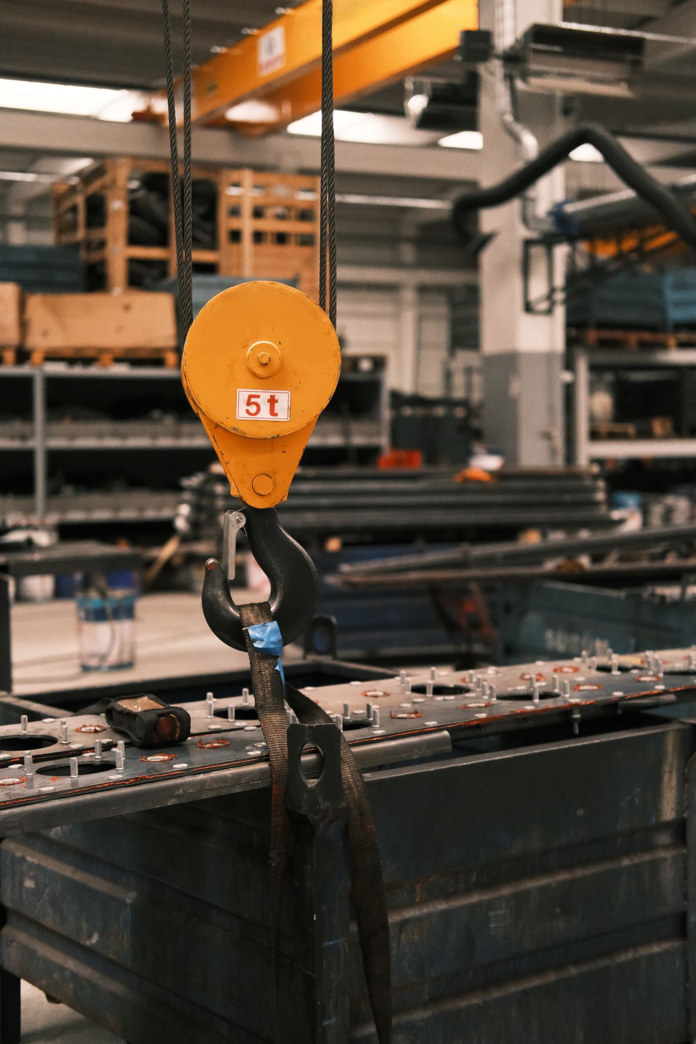
Freight elevators require the traction machine to be considered together with the actual load pattern.
A freight elevator carrying distributed palletized goods does not create the same operating condition as a car that regularly receives concentrated machinery, wheeled equipment, or vehicle loads. Rated load remains essential, but the complete elevator design must also account for how the load enters the car, how the car structure reacts, and how often the elevator operates under demanding conditions.
JAFITA’s strongest supplier evidence is in freight elevators. The company identifies freight-elevator production as a core manufacturing strength and describes long-term OEM cooperation in this product area. That experience makes freight elevator projects an important context for traction-machine coordination.
The current uploaded materials, however, do not publish JAFITA traction-machine model codes, motor ratings, sheave ranges, brake data, encoder types, or delivered machine ranges. The machine for a freight project therefore needs to remain tied to the approved complete-elevator configuration rather than being presented as a universal JAFITA traction-machine series.
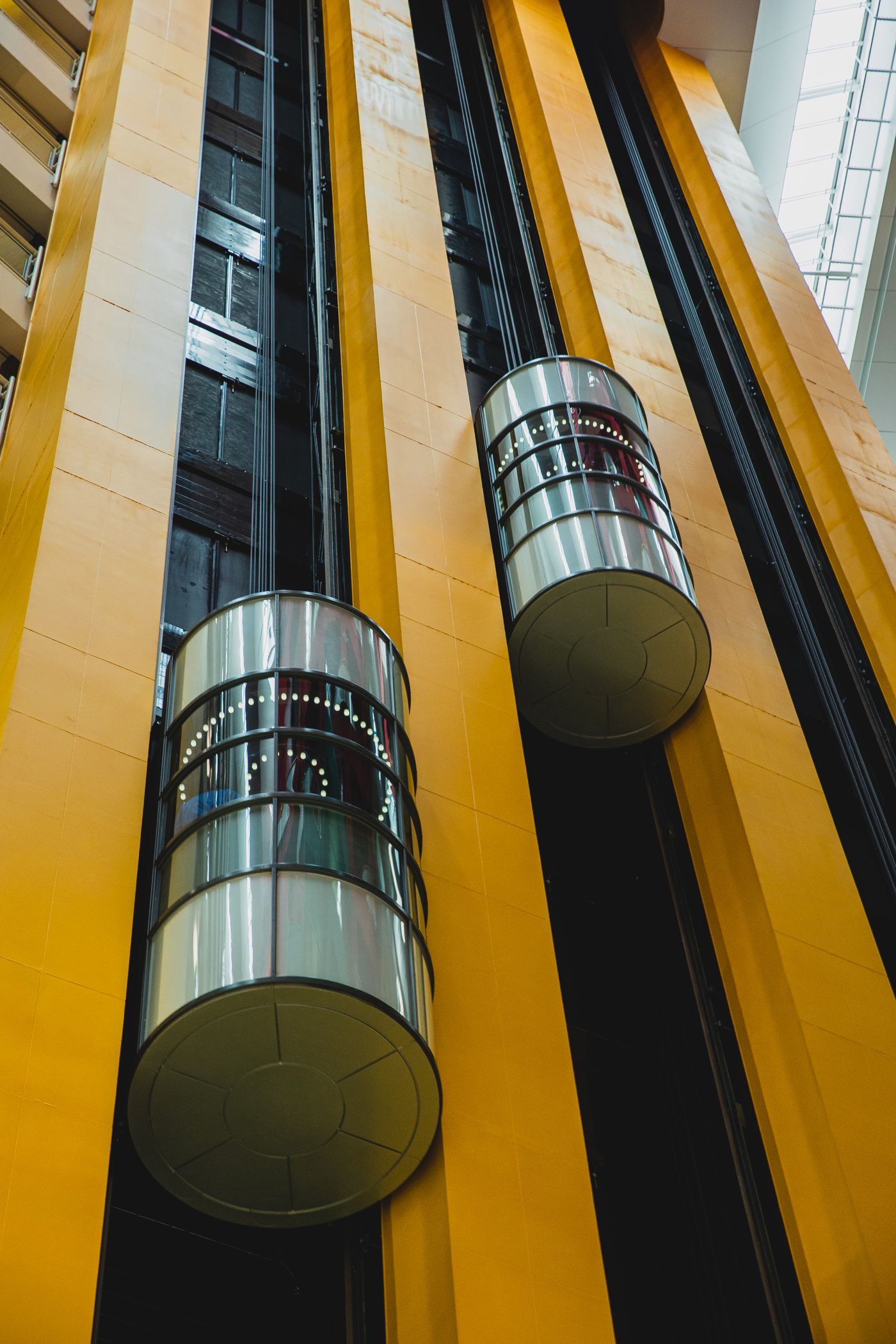
As rated speed and travel increase, traction-machine selection becomes more dependent on the complete dynamic design.
Machine torque and speed remain important, but ride behavior, acceleration and deceleration, rotating inertia, suspension mass, compensation, heat generation, drive control, braking, and system resonance can become increasingly important. The traction machine should therefore be considered with the inverter, controller, suspension, car and counterweight masses, guide system, and building interfaces.
JAFITA’s brochure presents a High-Speed Elevator category, confirming that higher-speed passenger projects exist within the broader supply scope. The current supplier documents do not publish the numeric speed range or the traction-machine platform used for that category.
For procurement, require the machine data to be tied to the approved elevator configuration. A machine advertised for “high speed” without the associated load, suspension, brake, feedback, sheave, and drive information is not enough for technical comparison.
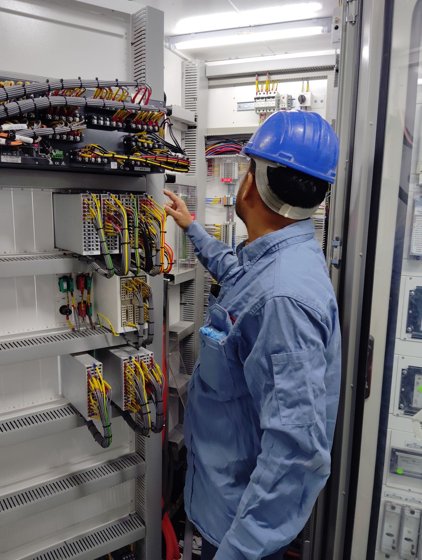
A modernization project often changes the machine at the same time as the drive or controller, but the retained equipment still defines many interfaces.
If the ropes remain, the new sheave must be compatible with them and with the reeving arrangement. If the inverter remains, the new motor and feedback system must work with its electrical and control capability. If the machine beams remain, the mounting and load paths must be checked against the new machine.
The brake also needs system-level review. Modern lift standards address protection against unintended car movement and ascending car overspeed as part of the wider safety design. A new machine brake may participate in those functions, but its suitability depends on the complete certified or verified system, not on the brake name alone.
Modernization should therefore begin with a retained-equipment matrix: suspension, controller, inverter, electrical supply, support steel, machine-space dimensions, car and counterweight data, and safety functions. Only then should a machine alternative be selected.
| Capability | Supplier evidence |
|---|---|
| Freight-elevator manufacturing foundation | JAFITA identifies freight elevator production as a core company strength. |
| OEM background | Company materials state that JAFITA has provided freight-elevator OEM services for multiple brands. |
| Named OEM history | KONE and ThyssenKrupp are named in the company’s long-term OEM history. |
| Factory-resource network | Company materials describe direct factory relationships developed through long-term cooperation, including Hitachi and XIO LIFT. |
| Passenger project scope | Current brochure presents Passenger Elevator and High-Speed Elevator categories. |
| Freight project scope | Current brochure presents Freight Elevator, Industrial Elevator, and Car Elevator categories. |
| International business | JAFITA has been engaged in elevator export business since 2008. |
| Engineering support | Company brochure presents an Engineering Service Team. |
| Lifecycle support | Company brochure presents lifecycle service support. |
| Company qualifications | Company portfolio presents a Special Equipment Production License and ISO 9001, ISO 14001, and ISO 45001 management-system certifications. |
The current supplier evidence supports JAFITA’s elevator-system and coordinated-supply background, but it does not establish a standalone JAFITA traction-machine model range. Model-level machine specifications should be added only when the corresponding supplier datasheets are available.
For an existing elevator, send the traction-machine manufacturer, complete model number, nameplate, elevator manufacturer and model, rated load, rated speed, suspension ratio, rope or belt data, traction-sheave dimensions, brake information, encoder information, motor electrical data, mounting dimensions, and photographs of the machine and installation.
Photographs should show the complete machine, nameplate, brake, encoder, traction sheave, rope path, motor terminals, connectors, base, and surrounding support arrangement. If the original general arrangement, machine drawing, controller schematic, or inverter data is available, include it.
For a new project or OEM program, provide the elevator type, rated load, rated speed, travel, suspension architecture, car and counterweight design basis, drive architecture, destination market, and required documentation. The traction machine should then be selected as part of the complete elevator system rather than sourced as an isolated motor.
JAFITA can coordinate the requirement through its elevator manufacturing, OEM, and factory-resource background. Final machine source, model, technical parameters, certification, and supply responsibility should be confirmed in the project-specific proposal.
A traction machine replacement should remain traceable from quotation through installation and later service.
The project record should preserve the machine manufacturer and model, serial or identification data where applicable, sheave specification, brake configuration, encoder type, motor parameters, mounting drawing, suspension data, inverter relationship, and any approved parameter set used during commissioning.
This is particularly important where the replacement is sourced through a coordinated supply network rather than from the original elevator manufacturer.
JAFITA’s company qualifications and export history support company-level supplier review. They do not establish traction-machine-specific testing, stock, certification, warranty, or interchangeability.
Price is influenced by elevator duty, machine architecture, motor rating, sheave and suspension interface, brake arrangement, encoder, mounting, quantity, documentation, destination, and shipping scope. A price based only on rated load or motor power is not enough for a reliable comparison.
No. Motor power is one field within a larger system. Suspension ratio, rated speed, sheave diameter, torque, brake, encoder, inverter, mounting, and traction conditions also have to match the elevator.
It can be technically possible in some modernization projects, but it should not be treated as a direct component substitution. Drive, feedback, brake control, mounting, support structure, and suspension geometry may also need changes.
Provide the sheave diameter, groove information, number and size of suspension means, rope or belt arrangement, reeving, and clear photographs. The original machine drawing is particularly useful because it establishes the sheave position relative to the base and suspension path.
The current uploaded supplier materials do not establish a standalone traction-machine model list. Machine source and model should therefore be confirmed against the specific elevator or replacement project.
Exact model, source, motor and brake configuration, encoder, machining or mounting requirements, quantity, technical confirmation, destination, and shipping method can all affect schedule. The current supplier materials do not publish one fixed traction-machine lead time.
Requirements depend on the complete elevator, destination market, component function, and applicable code. ISO 8100-1:2026 and ISO 8100-2:2026 provide international safety and component-verification frameworks within their scopes, while North American projects commonly use ASME A17.1/CSA B44.
That depends on the mechanical mounting, signal type, electrical interface, drive requirements, resolution, and controller architecture. Reuse should be confirmed as part of the machine-drive-control system rather than assumed.
Only after the suspension means, sheave geometry, condition, reeving, traction requirements, and applicable discard criteria have been evaluated. ISO 8100-2:2026 includes suspension and sheave verification topics specifically because these interfaces affect the safety of the system.
JAFITA’s supplier materials present engineering and lifecycle support but do not establish a universal overseas installation commitment. Removal, lifting, structural work, electrical connection, commissioning, testing, inspection, and local acceptance responsibilities should be defined for the project.
This page supports traction-machine identification and procurement. It does not turn an industry-general machine architecture into a JAFITA product specification.
The traction machine forms part of a complete elevator system. Changing it can affect the suspension means, sheave, brake, drive, encoder, control logic, supporting structure, traction calculations, commissioning parameters, and safety functions. The replacement should therefore be approved against the actual elevator rather than treated as a mechanically similar motor swap.
ISO 8100-2:2026 includes traction evaluation, suspension verification, sheave discard criteria, and other component calculations within its scope. That is the correct engineering context for machine selection: the traction machine and suspension system are connected design decisions.
JAFITA’s current evidence establishes freight-elevator manufacturing, OEM history, international project experience, factory relationships, and engineering support. It does not yet establish a standalone traction-machine catalogue. Until model-level supplier data is added, the final machine selection must remain project-specific.
