Use this page to determine whether an elevator drive matches the motor, encoder, controller, brake, power supply, duty, and retained system before replacement or modernization.
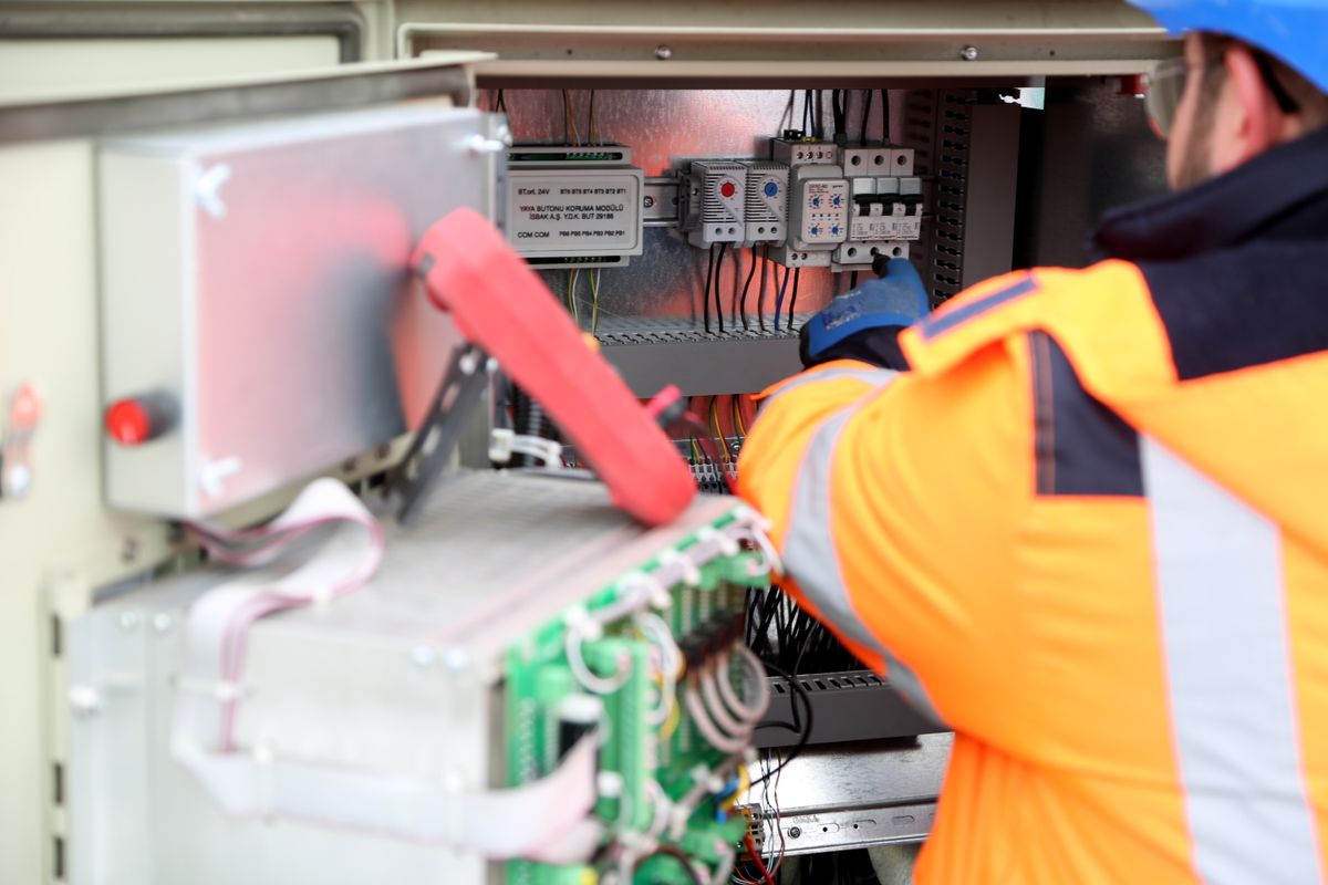
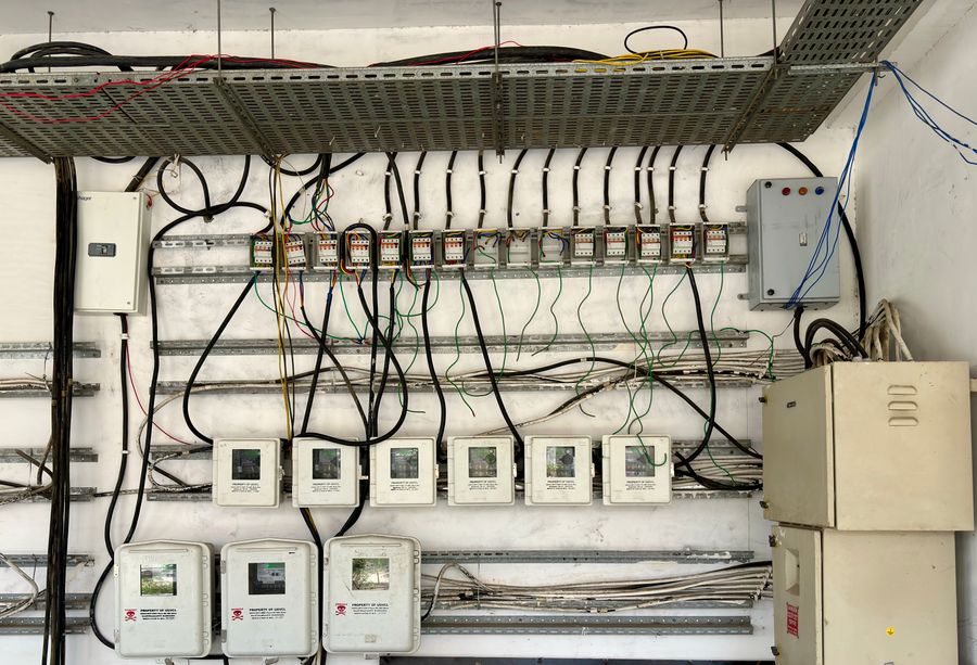
An elevator inverter can have the correct supply voltage and nominal power rating and still be wrong for the machine it is expected to control.
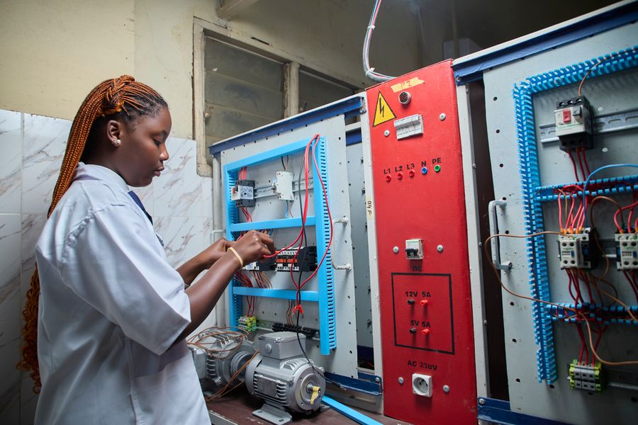
The first failure is motor mismatch. The drive has to control the actual motor architecture, not a generic kilowatt load. An induction motor and a permanent-magnet synchronous motor require different motor data, control behavior, feedback assumptions, and commissioning parameters. A replacement drive selected only from motor power may not produce the required torque, speed control, starting behavior, or stopping performance.
The second failure is feedback mismatch. Elevator motion depends on accurate control of speed and position. The drive may receive feedback through an encoder, resolver, or another device associated with the traction machine and control system. Signal type, supply voltage, resolution, connector, electrical interface, and parameter settings all matter. A mechanically unchanged traction machine can become unusable with a new drive if its feedback device cannot be read correctly.
The third failure is controller-interface mismatch. The controller commands movement, speed, braking, safety conditions, and stopping logic through defined electrical or communication interfaces. An incompatible drive may require a new controller or interface hardware even when its motor rating is suitable.
The first selection-driving field is motor type.
A traction elevator may use an induction motor or a synchronous motor, including permanent-magnet architectures used in many gearless systems. The drive must support the required motor-control method and be commissioned with the corresponding motor data. The motor nameplate is therefore a starting point, not an optional attachment.
Rated motor voltage, current, frequency, power, speed, and other manufacturer data need to be recorded. For synchronous machines, additional motor and feedback information may be required by the selected drive. For induction machines, the drive still needs enough data to establish an appropriate motor model and current control.
The second field is feedback. Some elevator systems use closed-loop control with an encoder or resolver; others may use different control strategies depending on the machine and application. The buyer should identify the feedback device, mounting, connector, signal type, and relationship with the existing controller and drive.
The third field is elevator duty. Rated load, rated speed, suspension ratio, car and counterweight relationship, acceleration and deceleration, starts per operating period, travel, and traffic pattern affect the torque and thermal duty demanded from the drive. A drive should not be sized from motor nameplate power without checking the application duty.
The fourth field is braking architecture. The project needs to establish how the drive handles deceleration energy and how the machine brake is sequenced. Depending on the system, energy may be dissipated through a braking arrangement or handled through another drive configuration. These are system-level decisions and should not be inferred from the word “inverter.”
The fifth field is controller interface. Direction commands, run enable, speed reference, brake sequence, inspection operation, leveling, fault reset, status feedback, and other functions need a defined signal path.
Verification fields include: Input supply, output rating, enclosure, cooling, terminals, communications, encoder interface, braking hardware, EMC-related installation requirements, parameter files, software revision, commissioning tools, and documentation.
A useful drive selection starts by reconstructing what the motor has to do throughout the elevator cycle.
The first input is the traction machine and suspension system. Record the motor data, traction-sheave relationship, suspension ratio, rated car speed, rated load, car mass where available, counterweight or balance information, and the expected direction of the most demanding operating condition.
The next input is motion profile. Elevator drives do more than run a motor at constant speed. They control acceleration, constant-speed travel where available, deceleration, approach, leveling, and stopping. The required torque and current can therefore vary significantly during one trip.
Thermal duty must also be considered. An elevator that makes occasional trips in a private residence and a high-traffic passenger or freight elevator impose different operating patterns on the drive. Repeated acceleration and deceleration can create a different thermal requirement even when the nominal motor power is unchanged.
Feedback and brake sequencing then need to be mapped. The controller, inverter, motor feedback, and brake must agree on when torque is established, when the brake releases, how speed is monitored, and how the car is brought to a controlled stop.
Supply voltage, cabinet ventilation, ambient conditions, cable routing, grounding, and electromagnetic compatibility also affect the usable configuration.
The final drive rating and parameter set must come from the selected drive data and the actual elevator system.
Gearless machines place strong emphasis on the relationship between the drive, motor, encoder, and brake.
Permanent-magnet synchronous machines are commonly used in gearless elevator architectures. The drive needs the correct motor information and feedback data to establish torque at low or zero speed, control acceleration, maintain the intended motion profile, and coordinate brake release and application.
A replacement drive therefore has to answer several questions before installation. Can it read the existing encoder or resolver? Does it support the motor architecture? Can the controller exchange the required commands and status information with it? Does the brake-control sequence remain valid? Are the existing motor cables, feedback cables, and cabinet interfaces usable?
If the answer to several of these questions is no, the project is not a simple inverter replacement. It may require a coordinated drive, encoder, controller, and brake-interface modernization.
The current JAFITA supplier materials do not publish a gearless-drive model range or permanent-magnet drive specification. These configurations should remain tied to the actual complete-elevator proposal.
Existing geared elevators often use induction motors and older control architectures. A modernization project may seek to retain the traction machine while replacing an older drive or controller.
The decision driver is how much of the existing machine system can remain without creating a poor control match.
Record the motor nameplate, encoder if fitted, machine speed, brake data, existing drive model, controller interface, supply voltage, and the operating condition before modernization. If the old system has ride-quality, leveling, overheating, or fault problems, record those symptoms rather than assuming the inverter alone is responsible.
A new variable-frequency drive can change motor control, but it cannot correct every mechanical issue. Brake condition, gearbox wear, traction, bearings, guide condition, rope condition, and mechanical backlash remain part of the elevator.
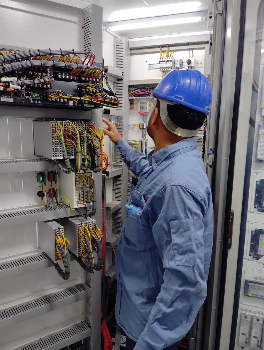
Freight elevators can create demanding drive conditions because the actual operating load may vary widely from trip to trip.
A lightly loaded upward trip, a heavily loaded downward trip, and repeated movement of concentrated freight create different torque and energy conditions. The drive needs to operate within the complete freight-elevator design rather than being selected from rated load alone.
JAFITA’s strongest manufacturing evidence is in freight elevators. Company materials identify freight-elevator production as a core strength and record long-term OEM cooperation. This gives JAFITA a direct system context for coordinating the machine, control, door, structure, and drive requirements of freight projects.
The current supplier documents do not publish drive model codes, overload curves, current ratings, braking hardware, encoder interfaces, or freight-specific drive ranges. The correct drive therefore remains part of the approved freight-elevator configuration.
For a freight modernization, provide the duty, motor data, machine model, load pattern, rated speed, controller, existing inverter, and recurring faults.
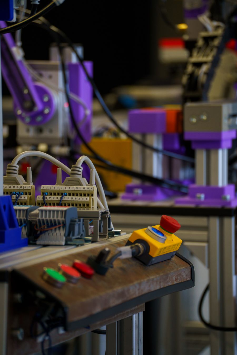
Passenger elevator drives are judged not only by whether the car moves, but by how consistently the complete system controls acceleration, deceleration, leveling, and stopping.
As speed and traffic increase, drive selection becomes more dependent on the motion controller, encoder, motor, braking architecture, rotating inertia, suspension system, and the required ride profile.
JAFITA’s brochure presents Passenger Elevator and High-Speed Elevator categories within its current product scope. This supports project-level coordination of passenger-drive systems, but the brochure does not publish the drive platform, motor pairing, control frequency, speed range, or commissioning method used in those categories.
A buyer comparing passenger-drive proposals should therefore ask for the complete motor-drive-control relationship rather than comparing inverter brand or power alone.
If ride quality is a requirement, define acceptance at the complete-elevator level because drive parameters are only one contributor to motion behavior.
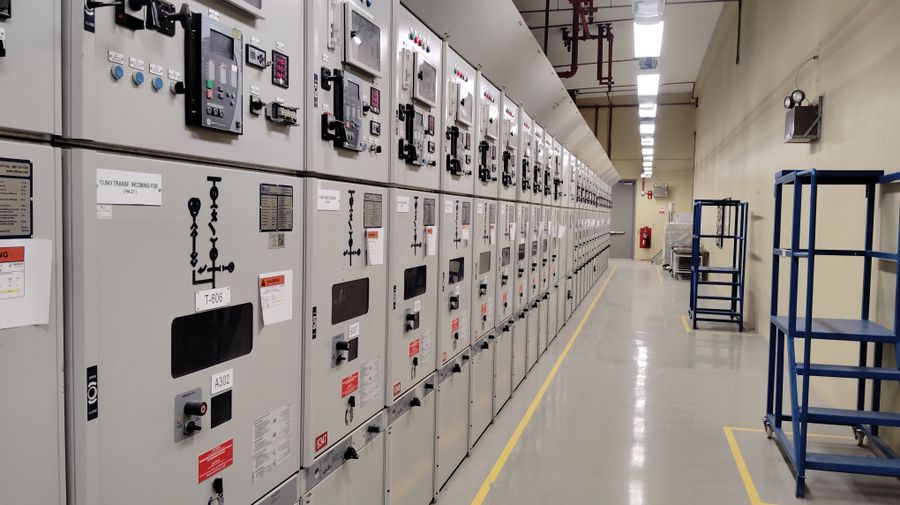
Regenerative drive technology can return electrical energy from certain operating conditions rather than dissipating all deceleration or overhauling energy locally. Whether that provides useful project value depends on the elevator duty, traffic pattern, drive architecture, building electrical system, power-quality requirements, and the way recovered energy is accepted by the installation.
A regenerative feature should not be evaluated from a percentage saving claim alone. The buyer needs the baseline, operating profile, measurement method, and whether the result refers to the drive, elevator, or complete installation.
The current JAFITA materials do not provide a regenerative-drive model, measured recovery rate, energy-saving percentage, or test method. Energy-related claims must therefore remain project-specific.
| Capability | Supplier evidence |
|---|---|
| Freight-elevator manufacturing foundation | JAFITA identifies freight elevator production as a core company strength. |
| OEM system background | Company materials state that JAFITA has provided OEM elevator services for multiple brands. |
| Named OEM history | KONE and ThyssenKrupp are named in the company’s long-term OEM history. |
| Factory-resource network | Company materials describe direct factory relationships developed through cooperation, including Hitachi and XIO LIFT. |
| Passenger project scope | Current brochure presents Passenger Elevator and High-Speed Elevator categories. |
| Freight project scope | Current brochure presents Freight Elevator, Industrial Elevator, and Car Elevator categories. |
| Home Elevator control context | Home Elevator presentation identifies an Intelligent Control System. |
| International business | JAFITA has been engaged in elevator export business since 2008. |
| Engineering support | Company brochure presents an Engineering Service Team. |
| Lifecycle support | Company brochure presents lifecycle service support. |
| Company qualifications | Company portfolio presents a Special Equipment Production License and ISO 9001, ISO 14001, and ISO 45001 management-system certifications. |
The supplier evidence supports JAFITA’s system-integration and elevator-project role, but it does not establish a standalone JAFITA inverter or drive catalogue. Drive brands, models, ratings, motor compatibility, encoder interfaces, and braking options should be added only from actual product datasheets.
For an existing elevator, send the inverter manufacturer, full model number, nameplate, power and current data, supply voltage, traction-machine manufacturer and model, motor nameplate, encoder or resolver model, controller model, brake data, and photographs of the installed cabinet.
Also provide the current fault condition. Include fault codes, when the fault appears, travel direction, load condition if known, whether the elevator operates in inspection mode, and whether any motor, encoder, brake, controller, or wiring work occurred before the fault began.
If the original drive parameters can be backed up, preserve them before removing the unit. Parameter records can contain motor tuning, speed profiles, I/O assignments, braking settings, and communication information that materially reduce commissioning uncertainty.
For modernization, state which equipment must remain. This allows JAFITA to determine whether the requirement is a drive-only replacement, drive-and-encoder package, drive-and-controller package, or wider control modernization.
For a new elevator or OEM program, provide the elevator type, motor architecture, rated load, rated speed, suspension arrangement, controller architecture, destination market, quantity, and documentation requirements.
A drive is not fully defined by the model printed on its front cover.
The project record should preserve the exact inverter model, hardware revision where relevant, software or firmware version, motor data, encoder interface, brake or braking hardware, controller communication method, I/O map, parameter file, wiring drawings, and commissioning record.
This becomes important years later when an apparently identical replacement unit arrives with a different firmware revision or default configuration. Without the original parameter record, the maintenance team may have to reconstruct motion and interface settings from the elevator itself.
JAFITA’s OEM background, freight-elevator manufacturing base, Engineering Service Team, lifecycle support, and export activity since 2008 provide a basis for coordinated project and replacement work. The current supplier documents do not publish drive-specific stocking, parameter-backup procedures, unit testing, fixed warranty, or software-support policy.
Company certifications support company qualification. They do not establish compatibility, functional safety, or electrical certification for a particular inverter.
Price depends on drive model, motor type, voltage, current and power requirement, encoder interface, braking architecture, communication, quantity, documentation, modernization scope, and destination. A price based only on kW may exclude the interfaces required to make the drive work with the elevator.
Not safely from that information alone. Match motor type, voltage, current, control method, encoder, controller interface, braking arrangement, duty, and installation requirements in addition to nominal power.
Only if the selected drive supports the motor architecture and the required feedback and control method. Motor and encoder data need to be confirmed before commissioning. Do not assume that a general-purpose induction-motor VFD is interchangeable with an elevator drive for a permanent-magnet machine.
Possibly. The new drive must support the encoder’s signal type, supply, resolution, connector or interface, and control requirements. If it does not, the project may need a new feedback device or a wider control-system change.
Sometimes. The new drive must accept the controller’s commands and return the required status and fault information. Discrete I/O, analog references, serial communication, brake sequence, and inspection operation all need to be checked.
ASME A17.5-2025 covers electrical equipment for elevators and related conveyances, including motor controllers and other electrical equipment within its scope. In North American projects, drive selection should therefore be evaluated within the wider A17.1/CSA B44 elevator-code framework rather than as a generic industrial VFD installation.
The current supplier materials do not publish a standalone inverter model list, power range, current range, encoder options, communication protocols, or motor pairings. These need to be confirmed against the specific elevator project or replacement requirement.
No universal drive MOQ is stated in the current supplier materials. Quantity, model, source, customization, project type, and documentation requirements affect commercial terms.
Exact drive model, motor pairing, encoder interface, braking hardware, quantity, parameter preparation, technical confirmation, destination, and shipping method can affect schedule. The current supplier materials do not publish one fixed lead time for all drives.
JAFITA’s materials present an Engineering Service Team and lifecycle support but do not establish a universal overseas commissioning commitment. Programming, motor tuning, site testing, inspection, local technician work, and remote support should be defined for the actual project.
An elevator inverter should not be treated as a generic industrial VFD selected by power alone.
The drive forms part of the elevator motion system together with the motor, feedback device, controller, machine brake, suspension, power supply, and safety architecture. Changing one of those elements can affect the parameters or interfaces of the others.
ASME A17.5-2025 identifies motor controllers and other electrical equipment as part of the elevator electrical-equipment safety framework in North America. The wider ASME A17.1/CSA B44 code then governs the elevator installation and operation within its jurisdictional scope.
General power-drive standards such as the IEC 61800 series can be useful background for concepts such as adjustable-speed drive safety and electromagnetic compatibility, but their published scopes and exclusions must be checked before applying them to a specific elevator drive. They should not be used to create JAFITA-specific claims.
JAFITA’s current evidence supports complete-elevator manufacturing in freight applications, OEM history, coordinated multi-category supply, international business, and engineering support. It does not yet establish a standalone drive range. Until model-level data is available, drive selection must remain tied to the actual elevator system.
