
Center-Opening vs. Telescopic Side-Opening Elevator Doors
Center-opening doors divide panel parking between both sides; telescopic side-opening doors concentrate it on one side. Choose the arrangement that preserves the required passage while fitting the available side spaces, entrance depth and complete equipment layout.
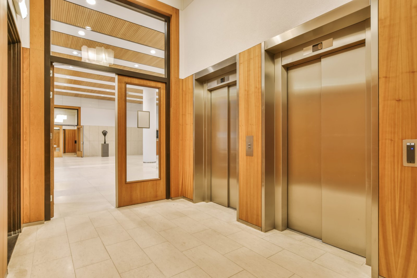
Hold the required clear opening, entrance position and project conditions constant when comparing the two layouts.
This guide is for architects, elevator buyers and modernization teams. JAFITA’s door-system page explains the broader geometry and interface requirements. Here, the focus is the space tradeoff between a two-panel center-opening arrangement and a two-panel telescopic side-opening arrangement.
| Comparison | Two-panel center opening (C2) | Two-panel telescopic side opening (T2) |
|---|---|---|
| Where panels park | Split between both sides | Concentrated on one side |
| Worth evaluating when | Both sides have room for the selected assembly | An obstruction lies close to one side and parking space is available on the other |
| Entrance depth | Can offer a shallower package; confirm the complete section | Can require more depth for overlapping panel tracks; confirm the complete section |
| Leaf travel, idealized | Each leaf travels about half the opening | Fast leaf travels about the full opening; slow leaf about half |
| Still to check | Both side spaces, depth, header and operator | Opening-side parking, depth, header and full layout |
About the examples: All dimensions and figures in the worked examples are hypothetical, chosen to demonstrate the method. They are not JAFITA product dimensions, tolerances or approval criteria. Final dimensions come from the drawing for the selected configuration.
Key Takeaways
- Center-opening doors use parking space on both sides. Telescopic doors park on one side, with entrance depth forming a separate part of the comparison.
- Check each side of the opening. In the example, a C2 layout requiring 1,860 mm fails within 1,970 mm of total space because the left side is 160 mm short.
- A 160–270 mm shift to the right resolves that width conflict. A depth conflict needs a change in the depth arrangement.
- Compare complete stop cycles on the same basis. In the simplified example, a 0.5-second opening advantage changes the combined opening, dwell and closing interval from 10.0 to 9.5 seconds.
What Are Center-Opening and Telescopic Elevator Doors?
With a two-panel center-opening door, the leaves meet near the center when closed and move in opposite directions to open. Space is required for the moving panels on both sides of the passage.
With a two-panel telescopic side-opening door, both leaves open toward one side and overlap on separate tracks in the open position. The leaves travel different distances in the coordinated movement. This is often described as a two-speed side-opening arrangement.
Specify both panel count and opening direction. A single-panel side-sliding door and a two-panel telescopic door have different movement and parking requirements.
Center-opening arrangements can also use telescoping panel groups: a four-panel center-opening door combines the two concepts. The C2-versus-T2 comparison here concerns the two-panel versions.
Use the manufacturer’s actual arrangement code and drawing in the quotation. Define the viewing direction for left-hand or right-hand opening, because a description without a viewpoint can be read differently by the building and elevator teams.
Confirm the elevator’s applicable code basis alongside the geometry. EN 81-20 addresses new passenger and goods-passenger lifts within its stated scope. The project team should identify the relevant equipment category, locally applicable edition and replacement requirements before specifying entrance performance.
Where Do the Door Panels Park?
These unscaled diagrams show parking distribution. Obtain tracks, overlaps, brackets and required clearances from the selected assembly drawing.
TWO-PANEL CENTER OPENING — viewed from the landing

Opening movement:          ← [left leaf] | [right leaf] →

Fully open:
[left parking zone] |<------ clear opening ------>| [right parking zone]
        BOTH sides need room for the selected door assembly.
TWO-PANEL TELESCOPIC SIDE OPENING — opening toward the right

Opening movement:          [fast leaf] → [slow leaf] →

Fully open:
[closing jamb]      |<------ clear opening ------>| [overlapping leaves]
                                                  parking concentrated
                                                  on the opening side
This makes a telescopic arrangement worth evaluating when an obstruction lies close to one side and more space is available on the other. Compare the full width and depth to see whether that parking advantage helps the project.
Panel overlaps, frames, operating equipment and mounting details determine the actual dimensions. Use the supplier’s complete envelope to set the builder’s opening.
Door Leaf Travel and Speed Compared
An idealized movement model helps explain the tradeoff. Ignore overlaps and mechanism travel for a moment, and call the clear opening W. Each leaf of a two-panel center-opening arrangement travels approximately W/2. In a two-panel telescopic side-opening arrangement, the fast leaf travels approximately W while the slow leaf travels approximately W/2, so both can park on the same side.
For the example 900 mm opening completed in three seconds of panel movement:
On small screens, scroll the table to read every column.
| Idealized arrangement | Travel of the relevant leaf | Mean travel speed for the assumed three seconds |
|---|---|---|
| C2: either center-opening leaf | 900 ÷ 2 = 450 mm | 450 ÷ 3 = 150 mm/s |
| T2: fast leaf | 900 mm | 900 ÷ 3 = 300 mm/s |
| T2: slow leaf | 450 mm | 450 ÷ 3 = 150 mm/s |
The fast telescopic leaf covers twice the distance of a center-opening leaf in this model. Its longer travel brings both leaves into overlapping positions on one side, so compare movement as well as panel count.
The table illustrates geometry; actual movement includes overlaps and mechanism travel. For a given moving mass, higher speed increases kinetic energy, so closing performance must suit the moving mass and applicable safety requirements. Door-operator technical reference
Four Elevator Door Dimensions to Compare
On small screens, scroll the table to read every column.
| Measurement | What it tells the buyer | Why the other measurements are still needed |
|---|---|---|
| Clear opening width and height | The usable passage with the door open | Add the panel parking, frame and operator requirements |
| Space required to the left and right | Whether the selected assembly fits around the opening at its proposed position | Check the available space on each side at the fixed entrance position |
| Entrance-package depth | How the car door, landing door and associated entrance assembly occupy the depth direction | An acceptable width layout can still conflict with the proposed car or shaft depth |
| Header/operator and mounting envelope | Whether the mechanism and its supports fit above and around the entrance | Include the complete assembly and its service access |
Mark the sill and frame reference lines on both alternatives. One supplier may quote a component dimension while another quotes the complete package. Comparing those numbers without their endpoints creates a misleading result.
For an existing elevator, obtain both the car-side and landing-side drawings. Coordinate the replacement arrangement with the geometry of retained equipment. JAFITA’s modernization guidance helps define what will remain and what will change.

Do Telescopic Doors Need a Deeper Sill?
Overlapping leaves move on separate tracks, making entrance depth a key part of a telescopic-door comparison. Check the complete car-door and landing-door package, with the intervening gap and mounting geometry identified. A component sill width and a complete entrance-package depth describe different boundaries.
Compare both sections against the same shaft outline and landing reference. If one package is deeper, show where that difference is accommodated: cabin depth, entrance position or shaft depth. The layout makes that tradeoff visible.
The worked example below uses a 120 mm package for Proposal A and a 180 mm package for Proposal B. These illustrative values let the reader follow the decision while keeping the final product dimensions tied to the selected drawing.
Worked Example: Enough Total Width, Too Little on One Side
Assume a project requires a 900 mm clear opening at a fixed landing position. The plan shows 320 mm of available space to the left and 750 mm to the right, measured within the defined door-assembly zones.
AVAILABLE WIDTH AT THE FIXED OPENING POSITION

Left obstruction                                      Right obstruction
|<-- 320 -->|<---------- 900 clear ---------->|<-- 750 -->|

Total: 320 + 900 + 750 = 1,970 mm
Compare two layouts whose stated side requirements include the relevant frame, panel and dimensional allowances.
On small screens, scroll the table to read every column.
| Requirement | Available | A: two-panel center opening | B: two-panel telescopic, opens right |
|---|---|---|---|
| Left-side space | 320 mm | 480 mm | 100 mm |
| Clear opening | 900 mm | 900 mm | 900 mm |
| Right-side space | 750 mm | 480 mm | 680 mm |
| Total of these three dimensions | 1,970 mm | 1,860 mm | 1,680 mm |
Proposal A needs 1,860 mm in total, less than the available 1,970 mm. It still conflicts with the left obstruction by 480 − 320 = 160 mm. Resolving that conflict requires a change to the entrance position or the left-side requirement.
Proposal B passes the side-space comparison with 220 mm remaining on the left and 70 mm on the right. Continue its assessment in the depth direction.
The coordinated entrance detail allows 160 mm for the package between agreed reference lines. Proposal A requires 120 mm; Proposal B requires 180 mm and is 20 mm too deep. The remaining problem is width for A and depth for B.
The appropriate response is to review a different package or a coordinated layout revision. Moving the opening, changing the entrance assembly or revising cabin geometry may be worth investigating, but each changes another project condition. The supplier and building designer must show what changes and which requirements are preserved.
If the opening can move, redraw both side spaces and review the passenger approach, landing entrance and car layout. Follow the width and depth checks with the header, mounting and retained-interface checks.
Can Shifting the Door Opening Solve the Conflict?
The failed comparison becomes useful when the team tests a defined change. Suppose the architect permits the opening to shift to the right without changing the two outer obstructions. Let the shift be x millimetres. The new available left space is 320 + x; the new right space is 750 − x.
For Proposal A’s 480 mm requirement on both sides:
Left condition: 320 + x ≥ 480, so x ≥ 160 mm.
Right condition: 750 − x ≥ 480, so x ≤ 270 mm.
There is therefore a geometrically feasible shift range of 160–270 mm for this simplified width check. A shift of 200 mm gives 520 mm on the left and 550 mm on the right, leaving 40 mm and 70 mm against the stated side requirements. Proposal A’s assumed 120 mm package also fits the 160 mm depth allocation, with 40 mm remaining.
The calculation identifies a specific design option. Proposal A becomes a candidate if the 200 mm entrance shift is compatible with the landing approach, cabin entrance, structure and other equipment. If the architecture permits only a 100 mm shift, the left-side conflict remains.
Proposal B needs a different depth arrangement or a change to the relevant car/shaft geometry. Keep the width remedy for A and the depth remedy for B separate when requesting revised layouts.
At either end of the 160–270 mm range, one side has zero margin against the hypothetical requirement. The project still has to account for any excluded uncertainty or construction variation. Choosing an interior point gives geometric room in this example, but the supplier’s actual drawing basis determines whether additional allowances are needed.
For a shaft serving several floors, also check the common-width method across floors. The entrance position must work with the usable shaft space through the full travel.
Clear Opening for Wheelchairs, Luggage and Carts
Door geometry is useful only if the resulting entrance serves the intended task. Define that task before asking the supplier to maximize the opening within a small shaft.
For a home elevator, identify the actual user, mobility aid and approach direction, then review how to measure a home elevator shaft. For a passenger elevator, include recurring luggage, strollers or service carts. Check the turn outside the door as well as the passage through it.
Keep clear opening and cabin dimensions unchanged in the first comparison where possible. If an alternative needs a smaller opening or usable cabin, show that reduction explicitly as a changed requirement.
Compare opening and closing behavior, moving mass, duty and protection arrangement for the offered equipment. Door operation interacts with the controller, users and the rest of the elevator.
Which Door Type Is Faster? Compare the Full Stop Cycle
Opening time matters, but the buyer experiences the full stop: door preparation and coupling, opening, passenger transfer and dwell, closing, and confirmation that the elevator can continue. Record which interval a supplier’s quoted time covers. A motor’s peak speed and an entrance’s complete operating cycle are different measurements.
In a simplified timing example, assume sequential intervals with no overlap. Proposal A opens in 2.5 seconds, dwells for 4.0 seconds and closes in 3.0 seconds: 2.5 + 4.0 + 3.0 = 9.5 seconds. Proposal B opens in 3.0 seconds with the same dwell and closing time: 3.0 + 4.0 + 3.0 = 10.0 seconds. The opening advantage is half a second within this roughly ten-second interval.
A real evaluation adds controller sequencing, coupling/unlocking, door protection, reopening events and the passenger task. Keep dwell, endpoints and conditions consistent between offers so the comparison isolates the difference being assessed. Select operating settings through the equipment’s approved commissioning process.
Panel construction also affects moving mass, operator selection and achievable performance. Keep the panel specification attached to the timing offer, and update both when the construction changes.
Replacing Door Operators in Elevator Modernization
In a replacement project, the car-door operator may work with retained landing doors at several floors. Check their condition, alignment and repair history floor by floor, documenting exceptions alongside the common arrangement.
Distinguish the layers of compatibility:
On small screens, scroll the table to read every column.
| Interface | Why dimensional fit alone is insufficient | Evidence needed for the proposed replacement |
|---|---|---|
| Car/landing-door coupling | The operator must engage and move the intended landing mechanism | Compatible mechanism and geometry identified in the replacement design |
| Landing-door locks and related contacts | The required locking and signalling functions need verification | Defined retained/replaced devices and the required verification procedure |
| Door controller and main lift controller | Commands, limits and reversing signals must be interpreted correctly | Documented interface and sequence for the installed equipment |
| Panels, guides and supports | Retained mechanical condition affects the new assembly’s operation | Condition assessment, exclusions and repair/replacement scope |
Review how the door controller and main lift controller exchange commands, limit indications and reversing signals. The replacement operator must participate in the intended sequence with the retained devices.
The acceptance record should identify retained components and their condition, cover the installed floor interfaces and required protection/locking functions, and record performance under the approved procedure.
Which Door Type Needs More Maintenance?
Compare the selected components and duty. Identify surfaces that collect debris, items requiring adjustment and the access available after cladding and finishes are installed.
The maintenance schedule should identify the applicable tracks, guides, transmission parts and connections, with the access needed for inspection and replacement. Use that schedule to compare maintainability on the actual configuration.
For a quotation, separate scheduled maintenance, replacement-part identification and access to remove major components. Compare reliability data only when the configuration, usage and observation period are stated.
Elevator Door Comparison Worksheet
Give both suppliers the same measured plan and required passage. Ask them to fill the same fields and mark any changed assumption.
On small screens, scroll the table to read every column.
| Comparison field | Proposal A | Proposal B |
|---|---|---|
| Manufacturer, model, arrangement code and drawing revision | ||
| Viewing direction and opening hand | ||
| Required clear opening width × height | ||
| Opening position relative to the common building reference | ||
| Required left-side and right-side space, with endpoints marked | ||
| Car-door, landing-door and complete package depth | ||
| Header/operator height, supports and maintenance access | ||
| Allowances included; tolerances or clearances specified separately | ||
| Resulting usable cabin dimensions | ||
| Retained landing equipment, coupling and controller interfaces | ||
| Project-required entrance performance and supporting documents | ||
| Building changes, exclusions and unresolved items |
Read each completed column as one configuration. If the proposed door, frame, finish or panel construction changes, obtain the corresponding revision rather than retaining an old dimension that happens to be favorable.
For modernization, attach the floor-by-floor interface assessment to this comparison sheet so the selected layout and the retained-equipment scope remain part of the same decision.
When to Choose Center-Opening vs Telescopic Doors
Evaluate C2 when both sides provide suitable parking space. Evaluate T2 when concentrating parking on one side helps the layout. In both cases, preserve the user’s opening and cabin requirements while checking depth, operator space and interfaces.
If both fit, compare timing, duty, maintenance access and installed scope. If a conflict remains, revise a defined constraint and show its effect on the complete layout.
Center-Opening vs Side-Opening Elevator Door FAQ
Are Center-Opening Elevator Doors Faster Than Side-Opening Doors?
Each C2 leaf travels about half the opening in the idealized model, which can help opening time. Compare the offered equipment’s actual cycle with the same dwell and closing conditions. The simplified example gives 9.5 versus 10.0 seconds; the complete stop also includes the applicable coupling and control sequence.
Do Telescopic Doors Allow a Smaller Shaft?
They concentrate parking on one side, which can help an asymmetric layout. Compare the complete shaft requirement because the entrance package can require more depth. Preserve the clear opening and usable cabin dimensions when comparing alternatives.
Is a Two-Speed Door the Same as a Telescopic Door?
For the two-panel side-opening arrangement discussed here, yes: “two-speed side opening” describes the coordinated fast and slow leaves of a two-panel telescopic door. State the panel count and opening direction explicitly, since other telescopic configurations also exist. The underlying speed relationship also appears in the two-speed definition in BIS’s public draft.
Which Door Type Is Better for a Home Elevator?
Choose the arrangement that preserves the passage and approach needed by the actual user while fitting both side spaces and available depth. Where a wall lies close to one side, a telescopic arrangement is worth evaluating early.
What to Send for an Elevator Door Quote
To request a comparison from JAFITA, send the country, elevator use, measured shaft and landing plans, target clear opening, entrance position, intended load or users, and any retained equipment details. Include photographs and available drawings for existing installations.
JAFITA’s door-system technical coordination can support a configuration-specific review of geometry, component identification and retained interfaces. Agree a response covering the proposed arrangement, complete entrance dimensions, operator/control interfaces and the items to retain or replace. Include the required drawing deliverables and commissioning responsibilities in the quotation scope.
Send the information through Request a Quote. A coordinated entrance proposal should connect the selected components to the space and interfaces they require.