
Home Elevator Shaft Size: A Measurement and Fit-Check Guide
Whether you call it a home elevator, home lift or residential elevator, its complete installation envelope must fit the finished building along the entire travel route. A room measurement, a cabin size and a floor opening describe different things. Before accepting a proposal, put the site’s available dimensions and the equipment’s required dimensions on the same drawing, with the same reference surfaces and floor levels.
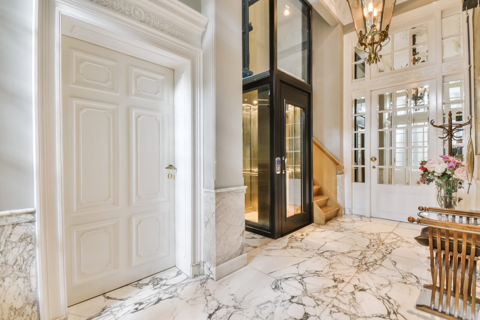
This guide helps homeowners, architects and contractors prepare that comparison. It builds on JAFITA’s home elevator planning guidance with a measurement record, a worked example and a way to handle dimensions that do not agree. Have the installer or a competent surveyor take measurements inside shafts, pits or near unguarded openings; owners can assemble plans, photographs and finish schedules.
About the examples: All dimensions and figures in the worked examples are hypothetical, chosen to demonstrate the method. They are not JAFITA product dimensions, tolerances or approval criteria. Final dimensions come from the drawing for the selected configuration.
Key Takeaways
- Cabin size, finished hoistway, rough opening and enclosure footprint describe four different spaces. Confirm which one a quotation means.
- Overlay every floor on one reference. In the example, each opening is at least 1,460 mm wide, but the common straight width is 1,445 mm.
- Deduct finishes still to be installed. Adding 25 mm of lining on each side reduces a 1,460 mm rough width to 1,410 mm.
- Measure pit depth, overhead and travel from finished floor levels. A 40 mm top-floor finish reduces the example overhead from 2,780 to 2,740 mm.
What Do Home Elevator Size Dimensions Actually Mean?
A quotation that says “1,500 × 1,500 mm” needs a drawing that identifies exactly which surfaces those dimensions describe.
On small screens, scroll the table to read every column.
| Dimension on the proposal | What it describes | What to compare it with |
|---|---|---|
| Clear internal cabin size | The space inside the car after the specified interior is installed | Intended users, mobility aids and carried objects |
| Finished hoistway width and depth | The clear building space bounded by the specified finished shaft surfaces | The surveyed shaft after remaining wall finishes and projections are accounted for |
| Structural or rough opening | An opening before the specified lining, frame or finish is installed | The corresponding construction opening, using the same stage of completion |
| Overall enclosure footprint | The outside of a supplied enclosure or supporting frame | Available building space, plus any installation and access allowances stated separately |
| Clear door opening | The usable passage when the door is open | The required passage and approach route, not the rough builder’s opening |
Each dimension answers a different planning question. The required shaft size follows the selected cabin, door arrangement, drive layout and equipment positions. Compare the complete layout, with each space identified.
Use preliminary dimensions to assess the available options and project-specific drawings to coordinate construction. Include the planned wall lining in the finished-hoistway calculation. A manufacturer planning reference on finished dimensions illustrates this distinction between the planning sketch and the installation drawing.
Ask the supplier to mark three items on the proposed layout: the dimension reference surfaces, any allowances already included, and anything the building contractor must provide outside that envelope. This prevents both omitted clearances and double-counted allowances.
Why Cabin Size Is Not Shaft Size
The unused-looking strip beside a cabin may contain the guide system, supports or other equipment; the strip at the entrance accommodates the selected car and landing-door arrangement. Moving the cabin sideways to clear one wall can put a bracket, entrance or another component into conflict elsewhere. Move and check the complete equipment layout together.
On the plan, identify the clear cabin, overall cabin, finished hoistway, rail-support references and entrance centerline separately. Locate where the equipment attaches to the building and where it meets the landing. Those fixed interfaces determine how much freedom remains to reposition it.
Three changes that appear similar on a sales sketch have different consequences:
On small screens, scroll the table to read every column.
| Proposed change | What it can address | What must be re-established |
|---|---|---|
| Reduce the usable cabin | A conflict involving the moving car or the complete equipment envelope | Whether the user’s required space remains usable, and whether the equipment envelope actually becomes smaller |
| Change the entrance arrangement | A conflict at the landing or with door parking | Compare center-opening vs telescopic doors, including package depth, entrance centerline and approach space |
| Change the drive/support arrangement | A conflict in the equipment zone or at available support positions | A new complete layout and building-load schedule; old offsets cannot be carried over automatically |
An installation clearance depends on both the amount and the location of the space around the cabin. Check each equipment zone on the coordinated plan.
Which Standard Applies to a Home Lift?
Establish the destination and product category before comparing dimensions. ASME A17.1/CSA B44 addresses elevators and related conveyances in North America. EN 81-41 has a specific scope: vertical lifting platforms intended for people with impaired mobility. A home installation’s product classification determines which requirements the project team must assess. Confirm the applicable edition, local adoption and configuration with the responsible engineering and approval parties.
How to Measure a Home Elevator Shaft on Every Floor
Use One Common Plan Reference
Label the entrance side and the opposite side consistently. Record which drawing view defines left and right. Mark a fixed building grid or other survey reference that can be carried from one floor to the next.
At each landing, record width and depth at more than one position, along with columns, beams, ledges and other projections. A single tape measurement across the middle can miss a narrower section near the entrance. Record diagonals or other survey observations used to establish whether the opening is square, and have the surveyor establish wall alignment through the travel zone.
Use the smallest width and depth readings for initial screening, then overlay every floor to find the continuous vertical space. Two floor openings can each be wide enough while being offset from one another. Their positions on the common reference reveal the usable route.
Find the Usable Shaft Width Across All Floors
Consider this three-level survey example. All readings use the same horizontal origin, and all wall coordinates include the proposed finishes. The model uses parallel rectangular sections; the site survey must also capture projections and geometry between landings.
On small screens, scroll the table to read every column.
| Survey station | Left wall coordinate, mm | Right wall coordinate, mm | Local clear width, mm |
|---|---|---|---|
| Lower level | 0 | 1,500 | 1,500 |
| Middle level | 35 | 1,525 | 1,490 |
| Upper level | 20 | 1,480 | 1,460 |
Every opening is at least 1,460 mm wide. However, a single straight vertical rectangular envelope must stay to the right of every left wall and to the left of every right wall:
Common left boundary = largest left-wall coordinate = 35 mm.
Common right boundary = smallest right-wall coordinate = 1,480 mm.
Common width = 1,480 − 35 = 1,445 mm.
A proposed 1,450 mm envelope fails by 5 mm, although it appears to pass against every individual width. The relationship between floors reveals the conflict; a more precise measurement at just one floor would still leave that relationship unresolved.
Apply the same method to front and rear boundaries to obtain the common depth. For angled walls, irregular projections or a rotated layout, the surveyor and designer should overlay the actual boundaries. Use the rectangular calculation for the geometry it represents.
Position remains a separate constraint even after the common space is wide enough. If the example instead required a 1,430 mm-wide envelope, its left edge could lie only between 35 mm and 50 mm, because 1,480 − 1,430 = 50. An entrance or fixed support that demands a left-edge position of 20 mm would still prevent that placement. This turns “there is 15 mm spare” into a specific, testable placement range.
Deduct Wall Finishes from Rough Measurements
For every measured surface, mark its condition: structural wall, partly finished wall or final finished surface. Then record remaining lining, plaster, tile, protective panels or other work that changes the clear space.
For an initial rectangular-section check:
Predicted finished clear width = measured width − remaining left-side build-up − remaining right-side build-up.
Use the equivalent calculation for depth. Deduct only work still to be added. If the survey measures the final surface, record that value directly. Treat local projections and wall alignment separately in the common-space overlay.
The following is a proposed record format. Use one row for each measurement station, and add rows wherever the geometry or finish changes.
On small screens, scroll the table to read every column.
| Floor / station and direction | Reference surfaces / completion stage | Measured clear dimension, mm | Remaining build-up on each side, mm | Predicted finished clear dimension, mm | Required dimension and drawing revision | Difference / open issue |
|---|---|---|---|---|---|---|
| Example: L1, width at entrance | Structural wall to structural wall | 1,460 | Left 25; right 25 | 1,410 | Proposal A, Rev. 02: 1,440 | 30 mm short |
Attach the marked plan, measurement date, surveyor’s name and relevant photographs. Keep measured values distinct from values inferred from drawings. If a measurement is inaccessible or uncertain, mark it for survey rather than entering an estimate as a confirmed dimension.
How Much Dimensional Margin Is Available?
A measured surplus has little meaning until both sides of the comparison have a defined basis. Keep three categories separate:
- Space already consumed: the finished walls, measured offsets and permanent projections. Include these in the available geometry.
- Space the equipment already requires: its specified installation envelope, including whatever operating or installation allowances the drawing explicitly incorporates.
- Unresolved reductions in available space: measurement uncertainty and remaining construction variation that have not already been included.
For a conservative preliminary check, subtract identified adverse reductions from the apparent margin. Suppose a finished-space estimate exceeds the required envelope by 10 mm, but the team has agreed to reserve 6 mm for survey uncertainty and 8 mm for possible additional finish build-up. The usable comparison becomes 10 − 6 − 8 = −4 mm. The apparent fit is not established.
Set the reserves from the project’s survey and construction basis. Count each allowance once: the common envelope already includes measured wall offsets, and the equipment drawing may already include operating clearance. Resolve any unspecified allowance before accepting the margin.
How to Measure Pit Depth and Overhead Clearance
Floor finishes affect the vertical comparison as well as the horizontal one. Establish a finished floor level (FFL) for every landing and show whether it is existing, proposed or revised.
On small screens, scroll the table to read every column.
| Item | Reference to establish | Common source of disagreement |
|---|---|---|
| Pit depth | Lowest landing FFL down to the final pit floor, using the supplier’s drawing convention | The site measurement starts at the structural slab, or a future pit topping is omitted |
| Overhead | Top landing FFL up to the overhead reference identified by the supplier | The measurement starts at an unfinished floor or ignores a beam below the roof slab |
| Floor-to-floor height | One landing FFL to the next landing FFL | Different finish thicknesses at adjacent landings |
| Total travel | Lowest served FFL to highest served FFL | An architectural level is confused with a finished entrance level |
| Entrance head and sill position | Proposed door details tied to each landing FFL | Door openings are set out before floor build-ups are agreed |
Mark beams and other overhead projections, including their horizontal position. Measure available overhead to the lowest obstruction within the equipment or clearance zone identified on the selected layout.
Record the selected configuration’s pit and overhead requirements beside the measured values. Check shaft level, vertical alignment and squareness against that drawing so the horizontal and vertical comparisons describe the same installation.
Consider the effect of a revised top-floor finish. If a provisional overhead measurement was taken from the structural floor and the final floor rises 40 mm, available overhead to the same upper obstruction decreases by 40 mm. At the lowest landing, raising the landing FFL increases the distance down to an unchanged pit floor; raising the pit floor reduces that distance. Record both elevations so the direction of the change is clear.
Reconcile Finished Levels on One Section
These example elevations show why a finish change can help one dimension and reduce another. The lowest structural landing slab is the zero datum; positive values are above it.
On small screens, scroll the table to read every column.
| Reference | Elevation, mm | Basis |
|---|---|---|
| Lowest structural landing | 0 | Survey datum |
| Lowest landing FFL | +60 | 60 mm floor build-up |
| Top structural landing | +6,000 | Surveyed slab level |
| Top landing FFL | +6,040 | 40 mm floor build-up |
| Structural pit floor | −300 | Before remaining topping |
| Finished pit floor | −270 | 30 mm topping added |
| Controlling overhead obstruction | +8,780 | Agreed reference for this example |
The corresponding finished dimensions are:
- Travel: 6,040 − 60 = 5,980 mm. It is 20 mm less than the structural slab-to-slab height.
- Pit depth: 60 − (−270) = 330 mm. The landing finish adds 60 mm, while the pit topping consumes 30 mm.
- Overhead: 8,780 − 6,040 = 2,740 mm. The top-floor finish consumes 40 mm of the provisional 2,780 mm.
Calculate these dimensions from the recorded elevations. A late top-floor increase also moves the entrance sill and changes travel, so update all three interfaces on the same section.
For each beam, record its plan position and underside elevation. Use the beam that intersects the required equipment or clearance zone as the controlling obstruction.
Worked Example: Two Proposals That Don’t Fit
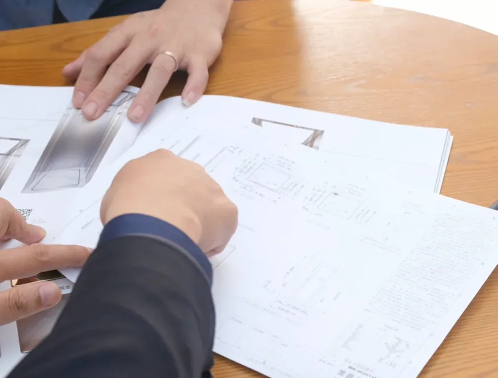
Using the same L1 reading shown in the record, the shaft measures 1,460 mm wide × 1,510 mm deep before the remaining finishes. The planned build-up is 25 mm on each of the four shaft faces.
On small screens, scroll the table to read every column.
| Screening calculation | Result |
|---|---|
| Finished width: 1,460 − 25 − 25 | 1,410 mm |
| Finished depth: 1,510 − 25 − 25 | 1,460 mm |
Assume both proposals state finished clear hoistway requirements with the relevant dimensional allowances included.
On small screens, scroll the table to read every column.
| Proposal | Required width × depth | Width comparison | Depth comparison | Initial result |
|---|---|---|---|---|
| A | 1,440 × 1,450 mm | 30 mm short | 10 mm remaining | Width conflict |
| B | 1,400 × 1,480 mm | 10 mm remaining | 20 mm short | Depth conflict |
The rough dimensions exceed both proposals, while the finished dimensions expose a different conflict in each. Compare each proposal as a complete equipment layout, keeping its width and depth requirements together.
For the 10 mm positive margins, account for measurement uncertainty, shaft alignment and the stated tolerances. Add any excluded allowance explicitly before accepting the comparison.
Now consider the vertical measurements. Assume the unfinished top-floor datum is 2,780 mm below the controlling overhead reference. The remaining top-floor build-up is 40 mm:
Predicted finished overhead = 2,780 − 40 = 2,740 mm.
If the selected layout requires 2,750 mm on that basis, the result is 10 mm short. Review the vertical conflict alongside the plan-view dimensions.
Send the marked discrepancies to the supplier and building designer. Possible revisions include a different equipment layout, entrance arrangement or approved building change. Preserve any required structural or fire-protection function when revising wall build-ups. Record the agreed change, update both drawings and repeat the affected measurements.
Check the Elevator Door and Access Route
An elevator can fit the shaft while still failing the user’s daily journey. Check how the user reaches the entrance, passes through it and leaves at the destination.
Show the actual approach with any wheelchair, walking aid, luggage or accompanying person relevant to the brief. Include nearby door swings, corridor corners and furniture. For entrances on different sides at different floors, mark each one on the plans; a front-and-rear arrangement has different interfaces from a single entrance.
JAFITA’s door-system guidance distinguishes usable opening from panel movement, jambs, sills and surrounding space. For a layout comparison, compare door panel parking and sill depth, then identify the corresponding builder’s opening on the drawing.
Keep a separate route for equipment delivery in the brief. A lift that fits its final position still has to reach that position through the building. Ask the supplier which packaged or assembled dimensions must be checked and identify restricted turns or access openings before ordering.
When Is the Shaft Ready for a Coordinated Layout?
Can the Shaft Wall Carry the Elevator Loads?
Before construction is fixed, check both the geometric envelope and the load path. The survey locates the wall; the structural assessment establishes how the wall, anchors and supporting structure receive the elevator loads.
Obtain the equipment reactions at the specified support points and confirm which factors are included in the load schedule. The building designer can then assess the receiving structure and connections on a defined basis.
Bring the support locations and reactions onto the same plan and section as the measured shaft. Record the wall construction, relevant supports and evidence available for an existing building, including the condition and connection capacity that need assessment.
This can change the fit decision. If a new support frame is required inside the shaft, its actual envelope consumes space. If the proposed rail-support wall cannot be used, relocating the equipment may change the cabin and entrance positions. Resolve that change before treating a generous tape measurement as a construction release.
Close the Decision with a Coordinated Revision
Use the comparison to assign one of three outcomes:
- A dimensional conflict is confirmed. Identify its location and amount. Obtain an agreed equipment or building revision before treating that proposal as a fit.
- The dimensions appear adequate, but evidence is incomplete. Obtain the missing survey, finish detail, alignment check or supplier allowance before accepting the affected comparison.
- The dimensional comparison is complete. Ask the supplier and building team to confirm the coordinated project drawings. Structural support, electrical provision, product classification and local approval remain separate parts of the project.
Freeze construction against the coordinated project drawing. Retain the survey, architectural and equipment-layout revisions together so later changes can be checked against the same baseline.
Home Elevator Shaft Size FAQ
What Is the Minimum Shaft Size for a Home Elevator?
There is no universal minimum. The required finished hoistway depends on the selected model, cabin, doors and equipment layout. Compare the exact configuration drawing with the building’s finished dimensions and the continuous space through all floors.
Should Shaft Dimensions Be Measured Before or After Wall Finishes?
Either stage works when the record identifies the measured surfaces. For structural-wall measurements, deduct the lining, plaster or tile still to be added. For completed surfaces, use the measured clear dimensions directly.
How Is Home Elevator Pit Depth Measured?
Measure from the lowest landing’s finished floor level down to the finished pit floor, following the selected drawing’s reference. In the example, a 300 mm structural pit, 60 mm landing finish and 30 mm pit topping give 330 mm of finished pit depth.
Why Can a Shaft Be Wide Enough on Every Floor and Still Fail the Fit Check?
The openings can be offset. For the parallel rectangular sections in this guide, subtract the largest left-wall coordinate from the smallest right-wall coordinate, all on one reference. The example gives 1,445 mm of common width even though every individual opening is at least 1,460 mm wide.
What to Send for a Home Elevator Quote
Send JAFITA the project country, intended users, floor plans, section, served floor levels and entrance direction at each stop. Attach the measurement record, remaining finish build-ups, pit and overhead information, photographs and the unresolved-dimension list.
If you already have a proposed layout, include its exact configuration and drawing revision. JAFITA can coordinate size configuration, door-opening method, car design and control selection within its Home Elevator supply scope.
For a defined configuration, agree a technical response covering the proposed layout, dimension reference surfaces, included allowances, required building provisions and unresolved site inputs. JAFITA can coordinate this information with the selected equipment route; specify the drawing deliverables and local design/installation responsibilities in the quotation scope.
Submit the plans and measurement record through Request a Quote, and request that configuration-specific response.
The result to work toward is one coordinated layout that the building team and JAFITA can identify by revision and compare with the measured site.